
Which devices and protocols support the alert channel of lightning-protection monitoring?
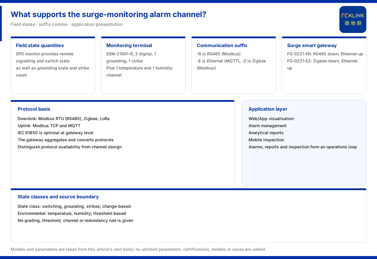
Direct answer: from the existing product material it can be confirmed that the alert channel of lightning-protection monitoring is not the function of one device but a link from field acquisition to application-layer presentation. One end of the link is the field device providing state quantities, such as the remote signalling, air-switch status, grounding status and lightning-strike count of the surge protective device monitor, and the switching values, grounding status and lightning-strike count of the intelligent lightning-protection monitoring terminal (a model such as ESM-21001-R), with another model also carrying temperature and humidity; the other end is the application layer, including Web/App visualisation, alert management, analysis reports and mobile inspection. In the middle, the communication method determined by the suffix and the gateway take over. The material gives no specification for alert grading, trigger threshold, notification channel (sound-light, SMS, App push) or channel redundancy and switching, so "how the link is built" can get definite information from the material, while "how alerts are graded and notified" still needs separate confirmation.
Understanding the alert as a channel rather than a switch is the starting point. The duty of the field device is to produce judgeable state quantities, the duty of communication and gateway is to deliver them, and the duty of the application layer is to present and manage them. If any link is missing, the alert cannot close the loop.
Field end: which state quantities become alert sources
The surge protective device monitor provides state quantities such as remote signalling, air-switch status, grounding status and lightning-strike count. These are discrete or cumulative states and are naturally suited to being alert triggers: remote signalling and air-switch status reflect connection and disconnection, grounding status reflects the connection of the grounding loop, and lightning-strike count reflects the occurrence and accumulation of lightning events.
The intelligent lightning-protection monitoring terminal likewise provides state quantities, including 2 switching-value channels, 1 grounding-status channel and 1 lightning-strike-count channel. Among them, ESM-21001-R additionally contains 1 temperature channel and 1 humidity channel, and its switching values are consistent with the other models. It can be seen that temperature and humidity are environment-class monitoring quantities, while switching values, grounding and lightning strikes are state-class monitoring quantities. The two classes mean differently for alerts: state-class quantities suit "alert on change", while environment-class quantities rely more on threshold judgement - and the material precisely gives no threshold rule for the latter.
Communication end: the suffix determines how the device connects
The material uses a general suffix to define the communication method: -R means RS485 (Modbus), -E means Ethernet (MQTT), and -Z means Zigbee (Modbus). The communication method of lightning-protection monitoring devices is chosen by suffix, meaning the same monitoring function can enter different communication links through different suffixes. Looking at the suffix first at selection is equivalent to first fixing how the device enters the alert channel.
Taking the lightning-protection smart gateway (a model such as FG-0221-ER) as an example, its downlink is RS485 and its uplink Ethernet; the other model FG-0221-EZ has a Zigbee downlink and an Ethernet uplink, and both are DC12V protocol-conversion types. Their role is to aggregate the downstream lightning-protection monitoring devices and forward them to the uplink side. The relation can be summarised as: the downstream device produces data, and the gateway converts the data from one link to another and aggregates it upward.
Protocol basis: from device downlink to device uplink
The communication protocol matrix given by the material states: device downlink includes Modbus RTU (RS485), Zigbee (Modbus) and LoRa; device uplink includes Modbus TCP and MQTT (which can run over Ethernet or 4G), with IEC 61850 optional at the gateway level. This set of protocols provides the basis of the alert channel: field devices access through the downlink protocol, and the gateway sends the data to the platform through the uplink protocol.
It is necessary to distinguish "protocol availability" from "channel design". The material confirms which protocols are available at which layers but gives no design specification such as channel redundancy, offline caching or failure retransmission. If a scheme is to state specific behaviours such as "automatic switching of the primary and backup channels" or "retransmission on disconnection", it should first confirm where those behaviours come from rather than inferring them from the protocol list.
Application layer: where alerts are presented and managed
In the general four-layer architecture of the monitoring system given by the material, the application layer includes Web/App visualisation, alert management, analysis reports and mobile inspection. Alert management sits at the application layer, showing that alert judgement and management are undertaken on the platform side, while field devices and the gateway deliver the data upward. This division is consistent with the link described above: the field provides state quantities, and the platform handles alert generation, display and handling flow.
The application layer also includes analysis reports and mobile inspection, showing that alerts are not an isolated function but part of a maintenance loop together with reports and inspection. The material does not develop the data flow detail between alerts, reports and inspection, but it can be confirmed that they sit on the same application layer and belong to the same level of capability.
Alert-design specifications the material does not give
First, no alert grading. The material does not say how many grades alerts have or what handling action each grade corresponds to.
Second, no trigger threshold. For quantities requiring judgement such as lightning-strike count, temperature and humidity, the material gives no threshold or cumulative criterion.
Third, no notification channel. Whether channels such as sound-light, SMS and App push exist and how they are configured is not stated by the material.
Fourth, no channel redundancy or switching rule. Design content such as primary and backup channels, disconnection behaviour and switching conditions is not given by the material.
These four points all belong to the design level of the alert channel. What the material can answer is "which data sources exist, which protocols they use and where they are presented", and what it cannot answer is "how alerts are graded, triggered and notified". Writing the latter as a settled conclusion would exceed the product factual boundary.
A checklist to complete before implementation
1. List the alert data sources. Confirm model by model which state quantities a field device provides, distinguishing state-class from environment-class. 2. Determine the communication method by suffix. Choose -R, -E or -Z according to the site link conditions and confirm it matches the gateway downlink. 3. Determine the gateway aggregation relation. Clarify which devices go up through which gateway and whether the uplink protocol is Modbus TCP or MQTT. 4. Clarify the application-layer host. Confirm which platform level hosts alert management, reports and inspection, avoiding overlap or gaps. 5. Review alert grading, thresholds and notification channels separately. The material does not give these, and they should be confirmed separately on site and recorded.
Summary
The alert channel of lightning-protection monitoring is a link from field to application: field devices provide state quantities such as remote signalling, air-switch status, grounding status, lightning-strike count, switching values, temperature and humidity; the communication method is determined by the -R, -E and -Z suffixes, and the gateway handles aggregation and protocol conversion; the application layer completes presentation and management through Web/App, alert management, reports and inspection. What the material can support is the composition of this link and its protocol basis; what it cannot support is alert grading, trigger threshold, notification channel and channel-redundancy specifications.
For an engineer, the safe approach is to fix the data sources, communication and gateway relation first and then define the alert strategy together with the platform and the site; for review and delivery, one should check whether a scheme contains alert grading or thresholds that the material does not have. Keeping "link composition" and "alert strategy" apart makes a scheme both complete and within bounds.


