
Direct answer
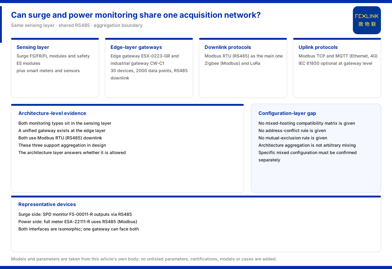
On whether lightning-protection monitoring and power-consumption monitoring can share one acquisition network, the product knowledge base leans towards "they can be aggregated" while drawing a boundary. What can be confirmed is that the intelligent edge-computing gateway (ESX-0223-GR) and the industrial gateway (CW-C1) both offer an access capability of 30 devices and 2000 data points and support RS485 downstream; lightning-protection monitoring modules and electrical-safety monitoring modules sit on the same perception layer; and the protocol matrix uses Modbus RTU (RS485) as the common device downlink protocol, with Modbus TCP, MQTT or IEC 61850 optional at the gateway uplink. The material gives no compatibility matrix, address conflict or mutual-exclusion rule for hanging both kinds of monitoring on the same gateway. What can therefore be said is that the two kinds of monitoring can enter one communication system through a unified gateway; what cannot be said is that any model can be mixed directly. This article explains the product basis for aggregation and makes clear this last boundary.
1. The two kinds of monitoring share the perception layer
The product knowledge base summarises the monitoring system as a four-layer architecture of perception, edge, platform and application. The perception layer contains both the FS, FR and FL series modules for lightning-protection monitoring and the ES series modules for electrical-safety monitoring, plus smart meters and sensors. Placing the two kinds of monitoring on the same layer is the starting point of the question "can they share one acquisition network".
Putting the two kinds of module on the same layer shows they face the same kind of data-aggregation need: both acquire quantities from the field and both need to go up through the edge layer. The material accommodates both in one architecture diagram rather than listing them as two unrelated systems.
2. The two kinds of gateway at the edge layer
At the edge layer, the material lists the lightning-protection smart gateway alongside ESX and CW gateways, as well as industrial wearables and cloud PLCs, with the duties of protocol conversion, edge computing and local caching. This means lightning-protection and power monitoring can enter the same communication system either through their own gateways or through a unified gateway.
On access capability, the intelligent edge-computing gateway and the industrial gateway both give a definition of 30 devices and 2000 data points, with RS485 downstream. Counting the module quantity of both kinds of monitoring inside this ceiling is one precondition for judging whether they can share one aggregation point; the material gives the capability ceiling, and configuration rules still have to be set separately.
3. The common downlink protocol
The communication protocol matrix of the product knowledge base lists: device downlink mainly uses Modbus RTU (RS485), Zigbee (Modbus) and LoRa; device uplink mainly uses Modbus TCP and MQTT (Ethernet, 4G), with IEC 61850 optional at the gateway level. Modbus RTU (RS485) is the downlink protocol listed in common by the two kinds of monitoring.
The existence of a common protocol shows the two kinds of module speak the same "language" at the interface level, which is the basis of aggregation. But a consistent protocol is only a necessary condition and does not automatically mean they can be mixed; address, polling and mutual-exclusion matters at the configuration level are not developed by the material.
4. Outputs of a representative device on the lightning-protection side
Taking the surge protective device monitor (FS-00011-R) as an example, the material lists that it outputs leakage current, voltage, temperature, lightning-strike count and lifetime-estimation data through RS485 and other communication. This shows that devices on the lightning-protection monitoring side are themselves acquisition terminals using RS485 as their main communication interface.
The data fields of such devices cover the operating state and event count of the SPD and are typical monitoring quantities. Once they enter the acquisition network and merge with power-side data at the edge layer, that is the concrete meaning of "sharing" at the data level.
5. Outputs of a representative device on the power side
On the power side, taking the all-parameter smart meter (ESA-22111-R) as an example, the material lists that it offers six current grades, is supplied across the series at AC220V with an OLED display, and outputs power-monitoring data over RS485 (Modbus). It also uses RS485 and Modbus, consistent with the lightning-protection side at the interface level.
Placing the representative devices of the two sides side by side shows they are isomorphic at the communication layer: both use RS485 and both can use Modbus. This explains why a unified gateway can in principle face both kinds of device without designing a separate link for each.
6. Common protocol and unified aggregation
The material does not directly give a "lightning-protection plus power" shared combination in its typical application scenarios, but it gives several separate combinations. Conversely, the two layers of evidence, architecture and protocol, support the statement that the two kinds of monitoring can be aggregated on the same protocol family: both sit on the perception layer, both can use RS485 downstream, and a unified gateway exists at the edge layer.
It must be stressed that the landing point of this statement is "aggregation", not "arbitrary mixing". The systematic description of the material is enough to support a merge judgement at the architecture level but not a direct replacement or arbitrary stacking at the configuration level.
7. Material boundary: no compatibility matrix
The product knowledge base gives no compatibility matrix, address-conflict rule or mutual-exclusion rule for hanging lightning-protection monitoring and power monitoring on the same gateway. It states only that the two share the perception layer and the RS485 and Modbus RTU downlink protocol. The answer to "can they share one acquisition network" is therefore affirmative at the architecture level and has no material conclusion at the specific configuration level.
Keeping the two apart avoids two misreadings: one is to treat "on the same layer" as "can be mixed directly", and the other is to treat "missing configuration rules" as "cannot be aggregated". The material supports half of the former and leaves a blank in the latter.
8. Contrasting architecture evidence with configuration gaps
Splitting the evidence into two layers makes the judgement much clearer. The architecture layer has three supports: the two kinds of monitoring share the perception layer, a unified gateway exists at the edge layer, and the downlink shares Modbus RTU (RS485). These three show that "aggregation" holds in system design. The configuration layer has nothing in the material: no compatibility matrix, no address rule, no mutual-exclusion statement.
The two layers do not contradict. The architecture layer answers "is it allowed by the system", the configuration layer answers "how exactly to connect". The material explains the former and leaves the latter blank. The most accurate answer to "can they share one acquisition network" is therefore: they can be aggregated within a unified system, and the specific mixed configuration must be confirmed separately.
In project practice, this distinction affects the order of decisions. First confirm at the architecture level that the two kinds of monitoring can enter the same gateway and platform, then confirm device address, communication parameters and capacity usage item by item at the configuration level, and only then form an implementable scheme. Skipping the architecture judgement overstates feasibility, while skipping the configuration confirmation understates the implementation effort.
Scope and limitations
First, this article restates only what the product knowledge base lists. The four-layer architecture, the access capability of the two kinds of gateway, the protocol matrix, the outputs of the representative devices and the material boundary are all cited as recorded.
Second, the material gives no compatibility matrix, address conflict or mutual-exclusion rule for hanging lightning-protection monitoring and power monitoring on the same gateway; this article does not infer that they can be mixed directly and gives no address or polling configuration scheme.
Third, the access capability is cited as the listed definition of 30 devices and 2000 data points; this article does not calculate from it the number of devices that can be mounted in a specific project.
Fourth, the specific acquisition-network scheme must be fixed against the site device list, communication conditions and maintenance requirements; this article provides no selection or networking calculation.


