
Direct Answer
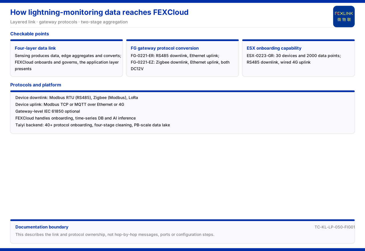
Lightning-protection monitoring data enters the FEXCloud IoT cloud platform along a layered chain: data moves from the perception layer through the edge layer into the platform layer's FEXCloud, then up to the application layer. On the device side, the FG lightning-protection smart gateway (FG-0221-ER) handles protocol conversion, with an RS485 downlink and Ethernet uplink; the FG lightning-protection smart gateway (FG-0221-EZ) in the same series has a Zigbee downlink and Ethernet uplink, and both use DC12V. On the edge side, the ESX intelligent edge-computing gateway (ESX-0223-GR) has an access capability of 30 devices and 2000 data points, with an RS485 downlink and a wired 4G uplink. On the protocol side, the communication protocol matrix specifies that the device downlink may use Modbus RTU (RS485), Zigbee (Modbus), or LoRa, and the device uplink may use Modbus TCP or MQTT carried over Ethernet or 4G, with IEC 61850 optional at the gateway level. The platform layer is carried by FEXCloud for device access, the time-series database, and the AI inference engine, while the Taiyi back end provides access for more than 40 protocols, four-level cleaning, and a PB-scale time-series data lake.
The documentation gives the protocol layers and link positions but not the per-hop messages, ports, or configuration steps between the gateway and the platform. This article explains the data chain, protocol attribution, and boundary on that basis.
1. The Data Chain in the Four-Layer Architecture
The general four-layer architecture of the monitoring system in the documentation is the perception layer, edge layer, platform layer, and application layer, and the platform layer is the FEXCloud IoT cloud platform. The data chain runs upward in this order: the perception layer produces data, the edge layer aggregates and converts protocols, the platform layer performs access and governance, and the application layer presents.
Placing FEXCloud in the platform layer rather than the edge layer is the key to understanding this chain. It does not face field devices directly but receives data aggregated by the edge layer. Each layer of the four has a clear division of labor, and data flows one way upward between layers. The edge layer produces no business conclusions, and the platform layer does not touch field wiring directly, a division that lets each segment of the chain be selected independently.
2. Protocol Conversion of the FG Gateway
The documentation lists two models of the FG lightning-protection smart gateway: the FG lightning-protection smart gateway (FG-0221-ER) has an RS485 downlink and an Ethernet uplink, and the FG lightning-protection smart gateway (FG-0221-EZ) has a Zigbee downlink and an Ethernet uplink, both with DC12V supply. Both handle protocol conversion, turning the downlink protocol into a form transmittable on the uplink.
The downlink difference lies in the access method: RS485 suits a wired bus, and Zigbee suits short-range wireless networking. The Ethernet uplink sends data to higher layers. During selection, first look at the field device's downlink interface and then at the uplink channel. The uniform DC12V supply also simplifies field power. The two models differ in the downlink interface while sharing supply and uplink, so field deployment differences concentrate on the downlink wiring. Both FG gateways share the same uplink, showing that the uplink channel is unified as Ethernet at the gateway level. If field devices use different downlink interfaces, only the matching downlink model need be chosen, and the uplink side stays consistent.
3. Access Capability of the ESX Edge Gateway
The documentation lists the ESX intelligent edge-computing gateway (ESX-0223-GR) with an access capability of 30 devices and 2000 data points, an RS485 downlink, and a wired 4G uplink. It aggregates the data of several devices into one gateway and sends it upward over wired 4G.
Device count and data-point count are two different definitions: the former states how many devices can be connected, and the latter the data scale that can be carried. Together they define the capacity boundary of an edge node. The 30 devices and 2000 data points are the two boundaries of access capability: the device count limits the connected objects, and the data-point count limits the reporting scale. Selection should check both together rather than estimating by device count alone.
4. The Communication Protocol Matrix
The communication protocol matrix in the documentation specifies that the device downlink may use Modbus RTU (RS485), Zigbee (Modbus), and LoRa; the device uplink may use Modbus TCP or MQTT carried over Ethernet or 4G; and IEC 61850 is optional at the gateway level. The matrix fixes the protocols available on each link and avoids protocol mismatch in the field.
Reading the downlink and uplink separately explains the need for protocol conversion: the downlink commonly carries a field bus or low-power wireless, while the uplink commonly uses Ethernet or a mobile network, and the two are not the same, requiring a gateway or edge node to bridge them. The matrix lists the two directions separately, meaning the two ends of one link may use different protocols. Protocol conversion is therefore not optional but a precondition for the link to be continuous.
5. Platform Layer and Taiyi Back End
At the platform layer, the documentation lists the responsibilities of FEXCloud as device access, the time-series database, and the AI inference engine, corresponding to the three tasks of access, storage, and inference. In the composition of the Taiyi intelligent control hub system, the Taiyi back end provides access for more than 40 protocols, four-level cleaning, and a PB-scale time-series data lake.
Both involve access and data governance, but they are described at different levels: FEXCloud is the general platform of the platform layer, while the Taiyi back end is the access and data layer inside the Taiyi system. Distinguishing the two avoids conflating the system's data layer with the platform's general layer. When placing FEXCloud and the Taiyi back end side by side, note that they describe different granularities: the former is a general platform-layer capability, the latter a data-layer component inside the Taiyi system. The documentation lists them separately and they should not be merged into the same level.
6. Two Levels of Aggregation from Device to Platform
Taking the chain apart, data undergoes two levels of aggregation from device to platform. The first is device to edge: the FG lightning-protection smart gateway converts the downlink protocol into a form transmittable on the uplink, so RS485 or Zigbee enters and Ethernet leaves; the ESX intelligent edge-computing gateway aggregates several devices with an access capability of 30 devices and 2000 data points and then uplinks over wired 4G. The second is edge to platform: after the data reaches the FEXCloud IoT cloud platform, the platform completes access, time-series storage, and inference.
The two levels correspond to two responsibilities: the edge side resolves protocol differences and field aggregation, and the platform side resolves unified access and data services. Understanding this helps consider the interface capability of the gateway and the access responsibility of the platform separately during selection, rather than asking one device to carry every segment.
7. The Documentation Boundary
The documentation gives only the downlink and uplink protocols of the FG gateway and the communication protocol matrix, and no per-hop messages, ports, or configuration steps from the FG gateway to FEXCloud. This article therefore explains the link and protocol attribution, not a configuration manual.
To implement configuration, the configuration documents of the gateway and platform should be used separately. This article's boundary stops at the protocol layers and device capabilities listed in the documentation.
Scope and Limitations
First, this article restates only what the product documentation lists. The four-layer data chain, the FG gateway protocols and supply, the ESX access capability, the communication protocol matrix, the FEXCloud responsibilities, and the Taiyi back-end composition are cited as written.
Second, this article does not infer message formats, port numbers, configuration steps, or field wiring, and does not derive implementation details from protocol names.
Third, IEC 61850 is cited as listed as an optional gateway-level uplink protocol; this article does not expand its clauses.
Fourth, this article gives no per-hop configuration flow from the FG gateway to FEXCloud, because that content is outside the factual boundary of the product documentation.


