Direct Answer
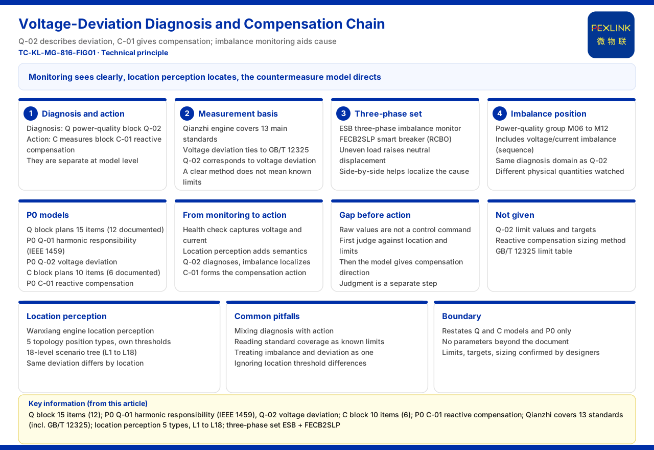
Voltage-deviation control in a distribution system can be split into two things: first use monitoring to see the deviation clearly, then use countermeasures to pull it back. In the product documentation, the diagnostic side corresponds to Q-02 voltage deviation of the Q power-quality block of the Tianyan engine, and the countermeasure side to C-01 reactive-power compensation optimization of the C energy-saving countermeasures block. The two are separate at the model level: Q-02 describes the deviation, and C-01 gives the compensation direction. The documentation further shows that the technical specifications of the Qianzhi engine cover 13 main standards including GB/T 12325, GB/T 14549, and GB/T 15543, among which the one directly related to voltage deviation is GB/T 12325. It should be said that the documentation gives no specific limit value or control target value for Q-02 and no calculation method for reactive-compensation capacity, so this article explains only the composition of the control chain and does not compute for the documentation.
For a site such as "distribution-automation three-phase control," placing imbalance monitoring alongside voltage-deviation diagnosis helps attribute the deviation more quickly to a three-phase distribution problem rather than broadly to system voltage fluctuation.
What Diagnosis and Countermeasure Each Are
The Q power-quality block of the Tianyan engine plans 15 models (12 in the documented definition), and its P0 first-release models include Q-01 harmonic responsibility division (based on IEEE 1459) and Q-02 voltage deviation. The C energy-saving countermeasures block plans 10 models (6 in the documented definition), and its P0 first-release model is C-01 reactive-power compensation optimization. Reading the two ends together, the basic order of control is to first judge the state of voltage deviation with Q-02 and then give the optimization direction of reactive compensation with C-01. The documentation does not state how parameters pass between the two models or the trigger condition of the compensation action.
The Measurement Basis of Voltage Deviation
The documentation lists GB/T 12325 as one of the main standards covered by the Qianzhi engine, and Q-02 corresponds to voltage deviation. This means that when discussing voltage deviation, the measurement definition refers to this standard. The documentation covers 13 main standards but does not list each name or give a correspondence table between each standard and sub-model. What can be confirmed is that voltage deviation is an object covered by this standard framework. Method basis and limit conclusion must be distinguished: even if the measurement method is clear, whether the deviation of a given bus exceeds the limit still depends on the applicable limit in that standard table, and the documentation does not attach that limit table.
The Relation Between Three-Phase Control and Voltage Deviation
The product combination given for the "distribution-automation three-phase control" scenario is the three-phase imbalance monitor (ESB) plus the intelligent circuit breaker with residual-current protection (FECB2SLP). This combination targets three-phase imbalance, which is closely related to voltage deviation: uneven three-phase load distribution increases neutral-point displacement and thereby affects the phase voltages. Placing imbalance monitoring alongside voltage-deviation diagnosis helps locate whether the deviation originates from system voltage fluctuation or local three-phase imbalance. The documentation gives no monitoring-parameter details of the ESB and does not state its data relation with Q-02, so the two cannot be inferred to coordinate automatically.
The Monitoring Position of the Imbalance Quantity
The power-quality physical examination sub-model group M06 to M12 of the Qianzhi engine contains monitoring items such as voltage imbalance and current imbalance (sequence components). Sequence components are a common way to describe the degree of three-phase imbalance, and listing them in the M06 to M12 group shows that quantifying three-phase imbalance belongs to power-quality physical examination. It and Q-02 voltage deviation both belong to the diagnostic scope of power quality but observe different physical quantities: one looks at the difference among the three phases, the other at the deviation of voltage from its rated value. The documentation gives no mapping between M06 to M12 and the Q block models.
How Location Awareness Participates in Control
The location-aware function of the Wanxiang engine maintains independent thresholds and risk models for 5 electrical topology position types and contains an 18-level scenario-location tree (L1 to L18). Applied to voltage-deviation control, this means a deviation of the same magnitude may correspond to different thresholds and risk levels at different positions of the distribution system. Location awareness gives diagnosis a spatial dimension rather than processing every measuring point by the same standard. The documentation lists neither the specific names of the 5 position types nor the correspondence between L1 to L18 and voltage deviation.
The Chain from Monitoring to Countermeasure
Stringing the known information together, the control chain is roughly: power-quality physical examination acquires voltage and current, location awareness assigns positional semantics, then Q-02 diagnoses the voltage deviation, where necessary combined with three-phase imbalance monitoring to locate the cause; finally it lands on C-01 reactive-power compensation optimization to form a countermeasure. In this chain, monitoring is responsible for "seeing clearly," location awareness for "locating," and the countermeasure model for "giving the direction," and none can be missing. The documentation gives no latency, priority, or closed-loop feedback between the stages, and this article does not supplement them.
What Is Still Missing Between Monitoring Data and Control Action
Between monitoring and countermeasure there is still a "judgment" step. The raw measured value of voltage deviation does not itself constitute a control instruction; it must first be judged against positional semantics and the applicable limit whether it deviates and to what degree, and then the countermeasure model gives the compensation direction. The documentation lists Q-02 and C-01 in different blocks, showing that this judgment step exists independently. For a control plan to be implemented, it should also clarify who reviews the judgment result, who performs the compensation adjustment, and how to re-test after adjustment. These processes belong to the implementation plan, which the documentation does not expand, and this article does not design for the project.
Limits and Capacity the Documentation Does Not Give
The documentation gives no specific limit value for Q-02 voltage deviation, no control target value, no calculation method for reactive-compensation capacity, and no limit table of GB/T 12325. These four are the inputs most needed when making a control plan. Their absence means any statement such as "deviation above what percentage must be controlled" or "compensate how many kvar" lacks documentation support. Limits and capacity should be determined by the design unit against applicable standards and field calculation.
Common Misunderstandings
The first misunderstanding is to conflate diagnosis with countermeasure, believing that installing monitoring equals completing control. The second is to misread the method coverage of GB/T 12325 as a known limit, ignoring that the documentation attaches no limit table. The third is to treat three-phase imbalance and voltage deviation as the same problem, ignoring that they monitor different physical quantities. The fourth is to ignore the threshold differences of location awareness and use one criterion for all measuring points. Separating these four makes the assumptions of the control plan sound.
Boundary Statement
First, this article restates only the model composition and P0 first-release models of the Q and C blocks, the standard coverage definition of Qianzhi, the product combination of the three-phase control scenario, the monitoring items of power-quality physical examination, and the description of location awareness, and does not extend to unlisted parameters. Second, the Q-02 limit, control target, and reactive-compensation capacity are documentation gaps that must be confirmed by the design and project units, and this article does not infer them. Third, this article does not constitute a power-quality compliance judgment or selection recommendation.