
Direct Answer
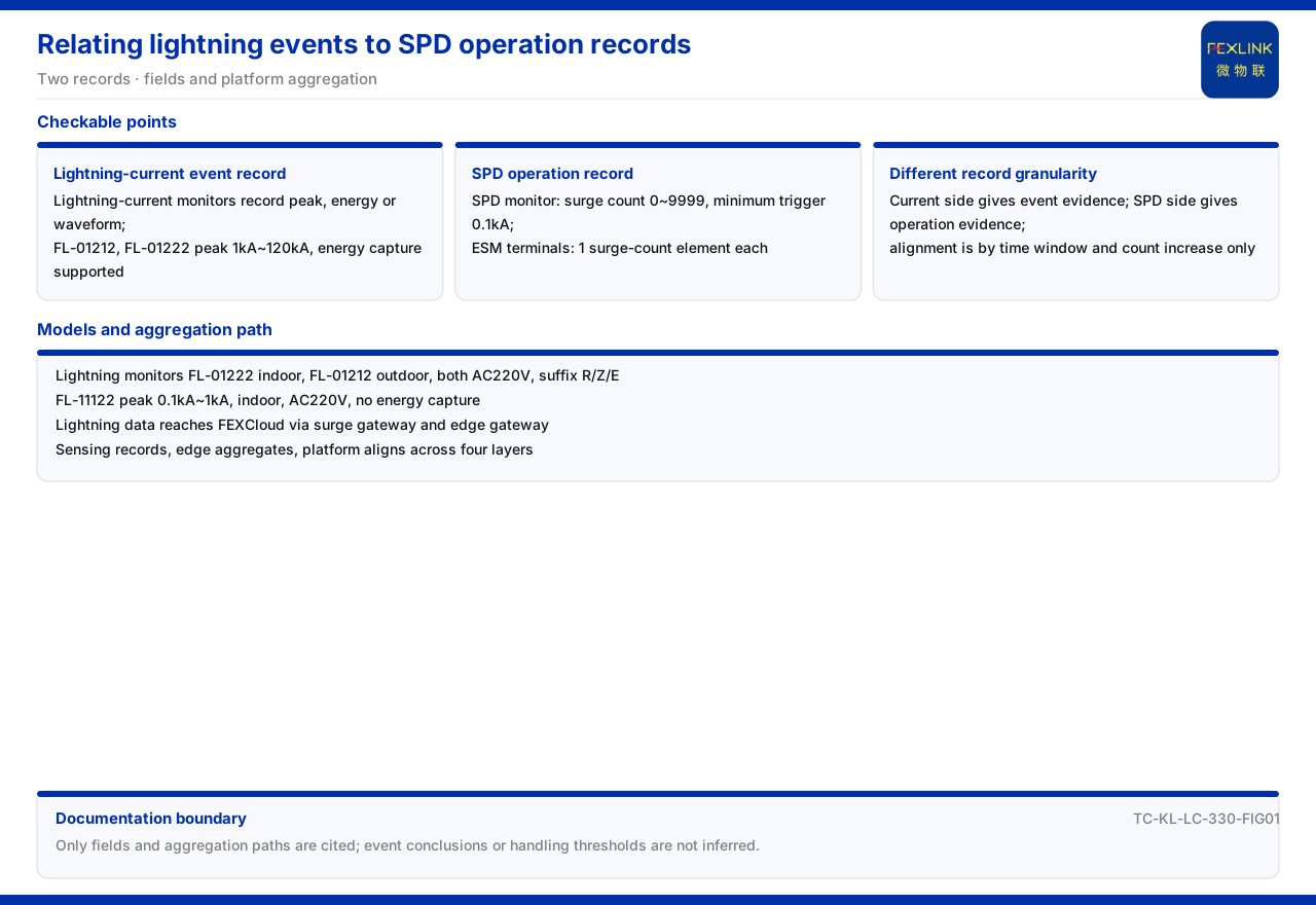
The record of a lightning event and the record of a surge protective device operation are two clues that come from different sources and can corroborate each other. In the product documentation, the lightning current / transient current monitor records lightning-current events, and its function steps include peak value, peak value plus energy, waveform, and waveform plus energy; the FS surge protective device monitor and the intelligent lightning-protection monitoring terminal both contain a lightning-strike counting element, which records the number of operations on the arrester side. Placing the two records on the same time axis makes it possible to judge whether the corresponding arrester operated during a given lightning event and which counting interval that operation falls into. This article explains only the fields, model definitions, and correlation method of the two records; it does not infer a specific event conclusion and does not give a decision threshold.
1. Two Records: Lightning-Current Events and Arrester Operations
In lightning-protection monitoring, "did a strike occur" and "did the arrester operate" are two different questions. The first is answered by the lightning current / transient current monitor: it measures the lightning current flowing through the monitored path directly and records the event's peak value, energy, or waveform. The second is answered by products carrying a lightning-strike counting element: the FS surge protective device monitor and the intelligent lightning-protection monitoring terminal record the number of operations while monitoring SPD status. The physical objects differ — one is the current event, the other the response of the protective device — but they share the dimension of time, so they can be aligned and compared on the platform side. Understanding the correlation starts with knowing what granularity each record can reach.
2. What Lightning-Current Monitoring Records
The model rule of the lightning current / transient current monitor encodes detection range, channel count, function, installation method, and power supply by digit; the function position contains four values: peak value, peak value plus energy, waveform, and waveform plus energy. This shows a progression from "peak only" to "peak and waveform together" within one series. On available models, the documentation records the lightning current / transient current monitor (FL-01222) as indoor installation and the lightning current / transient current monitor (FL-01212) as outdoor installation; both have a peak range of 1kA~120kA, support energy acquisition, use AC220V supply, and support the R, Z, and E communication suffixes.
A further model, the lightning current / transient current monitor (FL-11122), has a peak range of 0.1kA~1kA, indoor installation, AC220V supply, and no energy acquisition. The two parameter sets show that lightning-current monitoring is stepped by the measured current magnitude: the 1kA~120kA step covers a larger range and supports energy acquisition, while the 0.1kA~1kA step covers smaller currents without energy acquisition. During selection, first look at the expected current magnitude and whether energy data is needed, then at installation method and communication suffix.
3. What the Arrester Side Records
The arrester-side record centres on "lightning-strike counting." The documentation records that the FS surge protective device monitor contains a lightning-strike counting element, whose key parameters are lightning-strike counting from 0 to 9999 operations and a minimum trigger of 0.1kA, and states that this is the selection basis for arrester-operation recording. Two definitions must be held here: the counting range is 0 to 9999 operations, and the minimum trigger is 0.1kA — whether a current below that magnitude is counted depends on this minimum-trigger definition, not on an arbitrary setting.
The intelligent lightning-protection monitoring terminal also carries a lightning-strike counting element. The documentation records that every model contains this element at 1 channel, for example the intelligent lightning-protection monitoring terminal (ESM-21001-R) and (ESM-11112-R). The arrester side therefore records operation count and minimum trigger, not a complete current waveform; waveform belongs to the lightning current / transient current monitor. The two records have different granularity, so correlation can only align to the level of "did an event occur within the same time window and did the count increase"; the documentation gives no finer correspondence rule.
4. How the Two Records Reach the Platform
For the two records to be correlated, they must enter the same data system. In the general four-layer architecture of the monitoring system in the documentation, the perception layer contains monitoring modules of the FS, FR, FL, and ES series, and lightning-current data is uploaded to the platform layer through the edge layer. The documentation states that lightning-current data goes upward through edge devices such as the lightning-protection smart gateway and the intelligent edge-computing gateway and connects to the FEXCloud platform. The lightning current / transient current monitor and the monitoring terminal with lightning-strike counting therefore sit at different positions in the perception layer but converge to the same platform through the edge-layer gateways.
This architecture determines where correlation analysis happens: field devices produce the records, the edge layer aggregates and forwards them, and the platform layer places data from different sources together. Without the edge layer, both records might exist yet be hard to view side by side on one time basis. The correlation is therefore a complete data chain from perception layer to platform layer, not merely direct communication between two devices.
5. What Correlation Analysis Can Answer
With both records, several questions can be raised: within the time window of a lightning-current event, did the arrester-side lightning-strike count increase; if it did, where does it fall in the 0 to 9999 counting range; if it did not, was the 0.1kA minimum trigger not reached, or was that arrester not on the monitored path. These questions take the documented fields as their boundary: the lightning-current side provides peak value, energy, or waveform, and the arrester side provides count and minimum trigger.
The documentation does not state that "an increased count equals a normal arrester operation," nor does it give a rule for how high a count must be before handling is required; it provides only correlatable fields and a counting definition. Correlation analysis can therefore narrow the scope of investigation — separating "a strike occurred and the arrester has a record" from "a strike occurred but the arrester has no record" — but it cannot replace further verification of arrester condition. This article describes only the correlation path and does not infer the nature of a specific event.
6. Combinations in Typical Scenarios
In typical application scenarios and selection cross-references, the documentation lists the combination for tank-farm and petrochemical lightning-protection and explosion-proof scenarios as: explosion-proof grounding resistance monitoring, lightning-current monitoring, and surge protective device monitoring. This combination contains three kinds of records at once — resistance, event, and operation — showing that in real scenarios lightning-current recording and arrester recording are selection items that appear side by side rather than as an either-or choice. It also reflects the combined correlation: lightning-current monitoring provides event-level evidence, arrester monitoring provides operation-level evidence, and grounding monitoring provides status-level evidence.
The reading order can therefore be reduced to: first, confirm whether an event record or an operation record is required; second, for an event record look at the peak-value, energy, and waveform steps of the lightning current / transient current monitor, and for an operation record look at lightning-strike counting and minimum trigger; third, confirm whether both records converge to the same platform through the edge layer; fourth, align them within the same time window. Keeping to this order prevents two records of different granularity from being conflated.
Scope and Limitations
First, this article restates only what the product documentation lists, and its factual boundary is limited to the models and parameters of the lightning current / transient current monitor, the lightning-strike counting records of the FS surge protective device monitor and the intelligent lightning-protection monitoring terminal, and the four-layer architecture and typical-scenario records.
Second, the 1kA~120kA peak range, energy acquisition support, AC220V supply, and R, Z, and E suffixes of the lightning current / transient current monitor (FL-01222, FL-01212), and the 0.1kA~1kA, indoor, AC220V, no-energy-acquisition configuration of the lightning current / transient current monitor (FL-11122), are cited as listed in the model table; this article does not supplement unlisted models.
Third, the 0 to 9999 counting and 0.1kA minimum trigger are cited as listed in the key parameters of the FS surge protective device monitor, and the 1-channel lightning-strike counting element of the intelligent lightning-protection monitoring terminal (ESM-21001-R, ESM-11112-R) is cited as listed in the model table; this article gives no counting handling threshold.
Fourth, the division between the perception layer and the edge layer in the four-layer architecture, and the path by which lightning-current data goes upward through the gateway to FEXCloud, are cited as listed in the architecture record; this article does not supplement specific wiring or data-flow details.
Fifth, the tank-farm and petrochemical lightning-protection and explosion-proof combination is cited as listed in the selection cross-reference; this article does not expand it into a concrete project plan, and the latest product documentation and formal documents prevail in practice.


