
Direct Answer
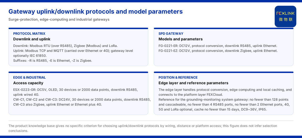
A gateway is the edge node in a monitoring system that connects field devices to the platform, and its uplink and downlink protocols determine how data is aggregated. The communication protocol matrix of the product knowledge base lists the device downlink protocols as Modbus RTU (based on RS485), Zigbee (Modbus) and LoRa, and the device uplink protocols as Modbus TCP and MQTT (which can be carried over Ethernet or 4G); at gateway level, IEC 61850 is optional. At the model level, the lightning-protection smart gateway (FG-0221-ER) uses twelve volts DC, protocol conversion, RS485 downlink and Ethernet uplink; the lightning-protection smart gateway (FG-0221-EZ) uses twelve volts DC, protocol conversion, Zigbee downlink and Ethernet uplink. On the edge-computing gateway side, the intelligent edge-computing gateway (ESX-0223-GR) uses five volts DC and an OLED display, can access thirty devices or two thousand data points, with RS485 downlink and wired and 4G uplink; the industrial gateways CW-C1, CW-C2 and CW-C3 use twenty-four volts DC and can access thirty devices or two thousand data points, with RS485 downlink (CW-C3 additionally including Zigbee) and Ethernet or Ethernet plus 4G uplink. The product knowledge base also gives reference parameters for the smart gateway of a grounding-resistance monitoring system. The product knowledge base does not give a specific criterion or threshold rule for choosing uplink and downlink protocols according to field wiring conditions, transmission distance or platform access method, so this article cites only the protocol list and model parameters and does not infer a protocol-selection conclusion.
1. Position of the Gateway in the System
In the general four-layer architecture of the monitoring system, the edge layer consists of the lightning-protection smart gateway, the intelligent edge-computing gateway, the industrial gateway, the industrial wearable and the cloud PLC, handles protocol conversion, edge computing and local caching, and connects upward to the platform layer FEXCloud. The gateway lies between the perception layer and the platform layer: it connects field devices downward and the cloud platform upward. Understanding this position helps distinguish the two classes of protocol — the downlink faces the device side and the uplink faces the platform side. The product knowledge base does not give the division-of-labour boundary of each gateway in the edge layer, so this article cites only the edge-layer composition and the gateway's position.
2. Uplink and Downlink Protocols and the General Suffixes
The communication protocol matrix of the product knowledge base lists the device downlink protocols as Modbus RTU (based on RS485), Zigbee (Modbus) and LoRa, and the device uplink protocols as Modbus TCP and MQTT (over Ethernet or 4G); at gateway level, IEC 61850 is optional. The general suffix table further gives the correspondence of communication methods: -R is RS485 (Modbus), -E is Ethernet (MQTT) and -Z is Zigbee (Modbus), and some products can optionally reserve 4G (MQTT). Putting the protocol matrix and the suffix table together confirms that the downlink protocols cover wired and wireless classes and the uplink protocols cover Ethernet and cellular networks. The product knowledge base does not give a criterion for choosing a protocol by wiring condition or transmission distance, so this article cites only the protocol and suffix lists.
3. Models and Parameters of the Lightning-Protection Smart Gateway
Consider the lightning-protection smart gateway first. The model table of the product knowledge base records: the lightning-protection smart gateway (FG-0221-ER) uses twelve volts DC, protocol conversion, RS485 downlink and Ethernet uplink; the lightning-protection smart gateway (FG-0221-EZ) uses twelve volts DC, protocol conversion, Zigbee downlink and Ethernet uplink. The two share the same supply and uplink, and the difference is on the downlink side, corresponding to RS485 and Zigbee respectively. That is, the same gateway, with the same protocol-conversion responsibility, can be typed by downlink protocol to access different classes of field device. The product knowledge base does not give the mounting count or cache duration of this gateway, so this article cites only the three items of supply, responsibility and uplink/downlink.
4. Parameters of the Edge-Computing Gateway and the Industrial Gateway
Next consider the edge-computing gateway and the industrial gateway. The product knowledge base records that the intelligent edge-computing gateway (ESX-0223-GR) uses five volts DC and an OLED display, can access thirty devices or two thousand data points, with RS485 downlink and wired and 4G uplink. On the industrial-gateway side, CW-C1, CW-C2 and CW-C3 all use twenty-four volts DC and can access thirty devices or two thousand data points, with RS485 downlink, where CW-C3 additionally includes Zigbee, and with Ethernet or Ethernet plus 4G uplink. The two classes of gateway thus give the same convention for access capability, differing in supply, display and the uplink/downlink combination. The product knowledge base does not give a substitution rule between the two classes, so this article cites only their respective parameters.
5. Reference Parameters of the Smart Gateway
The product knowledge base separately gives reference parameters for the smart gateway of a grounding-resistance monitoring system: mounting of no fewer than one hundred twenty-eight points with cascading, at least four RS485 channels, at least two Ethernet channels, optional 4G, 5G and LoRa, a data cache of at least fifteen days, a wide supply of nine to thirty-six volts DC and a protection rating of IP65. This group of parameters describes the reference configuration of a gateway in a particular system scenario and belongs to a different source from the supply, downlink and uplink conventions of the specific models above, so it should be cited separately and not applied directly to a specific model. The product knowledge base does not state which other scenarios this reference parameter applies to, so this article cites only its value conventions.
6. Reading Order and Boundaries
The above can be reduced to a reading order. First, confirm whether the object is a lightning-protection smart gateway, an edge-computing gateway or an industrial gateway, and read its supply, access capability and uplink/downlink protocols. Second, when protocol conventions are needed, cite the communication protocol matrix and the general suffix table, reading downlink and uplink separately. Third, if the gateway configuration of a grounding-resistance monitoring system is involved, cite the smart-gateway reference parameters but do not apply them to a specific model. Fourth, when system integration is involved, return to the edge-layer composition description and do not assign a layer to a device. The boundary to keep is that the product knowledge base gives no specific criterion or threshold rule for choosing uplink and downlink protocols according to field wiring conditions, transmission distance or platform access method; the relevant conclusions must be checked separately and must not be inferred from the product knowledge base.
Applicability and Limits
First, this article restates only what the product knowledge base lists, and its factual boundary is the record of the models and parameters of the lightning-protection smart gateway, the edge-computing gateway and the industrial gateway, and of the communication protocol matrix, the general suffix table, the general four-layer architecture and the smart-gateway reference parameters.
Second, the downlink Modbus RTU (based on RS485), Zigbee (Modbus) and LoRa and the uplink Modbus TCP and MQTT (over Ethernet or 4G) plus the optional gateway-level IEC 61850 in the communication protocol matrix are cited as listed; this article does not infer a protocol-selection criterion.
Third, the conventions for the communication suffixes -R, -E and -Z and the optional reservation of 4G are cited as listed in the product knowledge base.
Fourth, the twelve volts DC, protocol conversion, RS485 downlink and Ethernet uplink of the lightning-protection smart gateway (FG-0221-ER), and the twelve volts DC, protocol conversion, Zigbee downlink and Ethernet uplink of the lightning-protection smart gateway (FG-0221-EZ), are cited under the model table.
Fifth, the five volts DC, OLED, thirty devices or two thousand data points, RS485 downlink and wired and 4G uplink of the intelligent edge-computing gateway (ESX-0223-GR), and the twenty-four volts DC, thirty devices or two thousand data points, RS485 downlink (CW-C3 additionally including Zigbee) and Ethernet or Ethernet plus 4G uplink of the industrial gateway (CW-C1, CW-C2 and CW-C3), are cited under the model table.
Sixth, the mounting of no fewer than one hundred twenty-eight points with cascading, at least four RS485 channels, at least two Ethernet channels, optional 4G, 5G and LoRa, data cache of at least fifteen days, wide supply of nine to thirty-six volts DC and IP65 of the smart gateway of a grounding-resistance monitoring system are cited under the reference parameters, and this article does not apply them to a specific model.
Seventh, the edge layer consisting of the lightning-protection smart gateway, the intelligent edge-computing gateway, the industrial gateway, the industrial wearable and the cloud PLC, handling protocol conversion, edge computing and local caching and connecting to the platform layer FEXCloud, is cited under the general four-layer architecture.
Eighth, the product knowledge base gives no specific criterion or threshold rule for choosing uplink and downlink protocols according to field wiring conditions, transmission distance or platform access method; this article accordingly states no protocol-selection conclusion, and the latest product materials and formal documents prevail.


