
Direct Answer
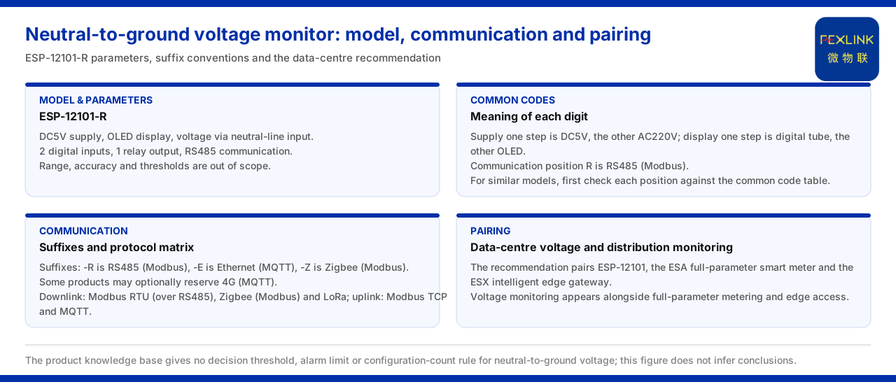
Neutral-to-ground voltage monitoring observes the voltage between the neutral line and the ground, and it is one monitored quantity in data-centre and distribution-monitoring scenarios. In the product knowledge base, the entry for the neutral-to-ground voltage monitor records the model and parameters: the neutral-to-ground voltage monitor (ESP-12101-R) uses a five-volt DC supply, an OLED display and a neutral-line input, carries two digital inputs and one relay output, and communicates over RS485. On communication conventions, the general suffix table of the product knowledge base records -R as RS485, -E as Ethernet and -Z as Zigbee, and notes that some products can optionally reserve 4G; the communication protocol matrix separately lists the downlink and uplink protocols. In the typical application scenarios of the product knowledge base, the row for data-centre neutral-to-ground voltage and distribution monitoring recommends a product combination of the neutral-to-ground voltage monitor (ESP-12101), the all-parameter smart meter (ESA) and the intelligent edge-computing gateway (ESX). The product knowledge base does not give a decision threshold or alarm limit for neutral-to-ground voltage, nor a configuration-quantity rule for scenarios of different capacity, so this article cites only the model parameters, the communication conventions and the recommended combination, and does not infer a decision conclusion.
1. Model and Parameters of the Neutral-to-Ground Voltage Monitor
Consider the product itself first. The product knowledge base records the model as the neutral-to-ground voltage monitor (ESP-12101-R), whose supply is five volts DC, whose display is OLED, whose voltage measurement object is a neutral-line input, with two digital inputs, one relay output and RS485 communication. These parameters show that the product performs neutral-to-ground voltage acquisition under a small supply convention and carries a small number of digital inputs and one relay output. The product knowledge base does not give the range, accuracy or decision threshold of this voltage, nor the control logic corresponding to the relay output, so these are outside the scope of this article. What can be confirmed is the five items of supply, display, input, output and communication, and these are the parameter boundary to keep when citing this model.
2. Correspondence Between the Model Code and the General Conventions
Next consider how the model code corresponds to the general rules. The general code for electrical-safety modules in the product knowledge base records one power-supply option as five volts DC and another as two hundred twenty volts AC; one display option as a digital-tube display and another as an OLED screen; and the communication digit R as RS485 (Modbus). The power-supply, display and communication values of the neutral-to-ground voltage monitor (ESP-12101-R) are consistent with this general code. That is, each digit in the model is not an arbitrary letter but is filled in position by position according to the general code table. With this understood, when reading the model of a similar product one can first check the meaning of each digit against the general code table and then return to the specific model table to confirm the parameters, avoiding confusion between the meanings of different digits.
3. Communication Suffix and Protocol Matrix
The suffix R of the neutral-to-ground voltage monitor (ESP-12101-R) corresponds to RS485. The general suffix table of the product knowledge base further explains that -R is RS485 (Modbus), -E is Ethernet (MQTT) and -Z is Zigbee (Modbus), and that some products can optionally reserve 4G (MQTT). At the system level, the communication protocol matrix lists the device downlink protocols as Modbus RTU (based on RS485), Zigbee (Modbus) and LoRa, and the device uplink protocols as Modbus TCP and MQTT (which can be carried over Ethernet or 4G); at gateway level, IEC 61850 is optional. Putting the suffix table and the protocol matrix together confirms that the communication of the neutral-to-ground voltage monitor falls on the device downlink side, while upward aggregation is carried by the gateway and the platform. The product knowledge base does not give a criterion for choosing uplink and downlink protocols according to site conditions, so this article cites only the protocol list and does not infer a selection conclusion.
4. Its Position in the System Layers
In the general four-layer architecture of the monitoring system, the platform layer is the FEXCloud IoT cloud platform, which handles device access, the time-series database and the AI inference engine; the application layer provides Web and App visualisation, alarm management, analysis reports and mobile inspection. A quantity such as neutral-to-ground voltage enters the edge layer and the platform layer from the field modules before visualisation and alarms are formed at the application layer. It should be distinguished that the product knowledge base does not explicitly assign the neutral-to-ground voltage monitor to the list of any one layer, so this article cites only the functional descriptions of the platform layer and the application layer and does not assign a layer to the product.
5. Typical Application Combination
In the typical application scenarios and selection comparison of the product knowledge base, the row for data-centre neutral-to-ground voltage and distribution monitoring recommends a product combination of the neutral-to-ground voltage monitor (ESP-12101), the all-parameter smart meter (ESA) and the intelligent edge-computing gateway (ESX). That is, in this scenario neutral-to-ground voltage monitoring, all-parameter energy metering and edge access appear as parallel selection items. This combination shows that neutral-to-ground voltage monitoring is not deployed in isolation but enters the edge layer together with the data acquisition for distribution monitoring. The product knowledge base does not give the wiring method, data flow or alarm linkage among the devices in this combination, so this article cites only the recommended combination itself and does not expand it into a specific project scheme.
6. Reading Order and Boundaries
The above can be reduced to a reading order. First, read the five parameters of the neutral-to-ground voltage monitor (ESP-12101-R) — supply, display, input, output and communication — and make clear that the range, accuracy and threshold are outside the scope of citation. Second, use the general code table to check the meaning of each model digit, then use the general suffix table to confirm the communication convention. Third, if system integration is involved, cite the communication protocol matrix and the functional descriptions of the platform layer and the application layer, without assigning a layer to the device. Fourth, if a scenario is involved, return to the selection comparison and confirm the recommended combination for data-centre neutral-to-ground voltage and distribution monitoring. The boundary to keep is that the product knowledge base gives no decision threshold, limit or alarm limit for neutral-to-ground voltage, and no configuration-quantity rule for scenarios of different capacity; the relevant conclusions must be checked separately and must not be inferred from the product knowledge base.
Applicability and Limits
First, this article restates only what the product knowledge base lists, and its factual boundary is the record of the neutral-to-ground voltage monitor's model and parameters, the general code for electrical-safety modules, the general suffix table, the communication protocol matrix, the general four-layer architecture and the selection comparison.
Second, the five-volt DC supply, OLED display, neutral-line input, two digital inputs, one relay output and RS485 of the neutral-to-ground voltage monitor (ESP-12101-R) are cited under the convention listed in the model table of the product knowledge base; no range, accuracy or threshold is added.
Third, the values of the power-supply, display and communication digits in the general code for electrical-safety modules are cited under the convention listed in the product knowledge base, for the purpose of checking the meaning of each model digit.
Fourth, the conventions for the communication suffixes -R, -E and -Z and the optional reservation of 4G, and the downlink and uplink protocol lists in the communication protocol matrix, are cited under the convention listed in the product knowledge base; this article does not infer a protocol-selection criterion.
Fifth, the functional descriptions of the platform layer FEXCloud IoT cloud platform and the application layer are cited under the convention listed in the general four-layer architecture of the product knowledge base; this article does not assign the neutral-to-ground voltage monitor to a layer.
Sixth, the recommended combination for data-centre neutral-to-ground voltage and distribution monitoring is cited as listed in the selection comparison of the product knowledge base, and this article does not expand it into a specific project scheme.
Seventh, the product knowledge base gives no decision threshold, limit or alarm limit for neutral-to-ground voltage and no configuration-quantity rule; this article accordingly states no decision conclusion or configuration quantity, and the latest product materials and formal documents prevail.


