
Direct Answer
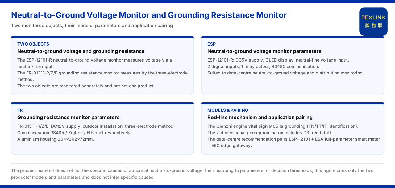
In data-centre and distribution-monitoring scenarios, neutral-to-ground voltage and grounding resistance are two objects requiring separate monitoring, corresponding to two different products. The neutral-to-ground voltage monitor (ESP-12101-R) measures voltage from a neutral-line input, has a DC5V supply, an OLED display, 2 digital inputs and 1 relay output, and communicates over RS485. The grounding resistance monitor (FR-01311-R and FR-01311-Z and FR-01311-E) has a DC12V supply, uses the three-pole method, is installed outdoors, and communicates over RS485, Zigbee and Ethernet respectively. In the typical application scenarios and selection comparison of the knowledge base, the data-centre neutral-to-ground voltage and distribution-monitoring row recommends the combination of the neutral-to-ground voltage monitor (ESP-12101), the all-parameter smart meter (ESA) and the edge gateway (ESX). It should be noted that the knowledge base lists no specific cause list for neutral-to-ground voltage anomalies, no cause-parameter correspondence and no decision threshold, so this article cites the two products' models and parameters separately and does not infer a specific cause.
1. First Distinguish Neutral-to-Ground Voltage from Grounding Resistance
Neutral-to-ground voltage and grounding resistance both sound related to "ground", but in the product system they are different monitoring objects. The neutral-to-ground voltage monitor measures the voltage between the neutral line and ground, with a neutral-line input; the grounding resistance monitor measures the resistance of the grounding body, using the three-pole method or the loop method. The former is a voltage quantity, the latter a resistance quantity, and their measurement principles and wiring objects differ. The knowledge base places the two under different product entries, giving models, supply and communication separately. Once the objects are distinguished, each later parameter has the correct owner: a voltage-range description points to the neutral-to-ground voltage monitor, while a measurement-method or installation-method description points to the grounding resistance monitor. Mixing the two easily applies a voltage convention to a resistance measurement.
2. Model and Parameters of the Neutral-to-Ground Voltage Monitor
Consider the neutral-to-ground voltage monitor first. The model recorded by the knowledge base is the neutral-to-ground voltage monitor (ESP-12101-R), with a DC5V supply, an OLED display, a voltage measurement object of neutral-line input, 2 digital inputs, 1 relay output and RS485 communication. These parameters show that this product completes neutral-to-ground voltage acquisition at a very small supply convention and carries a small number of digital inputs and one relay output. The knowledge base does not give the voltage range, accuracy or decision threshold, nor explain the control logic corresponding to the relay output, so these are outside the scope cited here. What can be confirmed is the five items of supply, display, input, output and communication, and these are the parameter boundary to hold when citing this model.
3. Model and Measurement Method of the Grounding Resistance Monitor
Now consider the grounding resistance monitor. The knowledge base records three models, the grounding resistance monitor (FR-01311-R) and (FR-01311-Z) and (FR-01311-E), all with a DC12V supply, outdoor installation, the three-pole measurement method, and communication over RS485, Zigbee and Ethernet respectively. The model rule further marks the code values of the detection principle and installation method: in the detection-principle tier, one value is the loop method and the other the three-point method; in the installation-method tier, one value is outdoor and the other indoor. This shows that the three-pole method and the loop method are two optional detection principles, and outdoor and indoor two optional installation methods. The knowledge base does not give the instrument's resistance range or accuracy, so this article cites only the value conventions of the measurement and installation methods and does not add range values.
4. Outline and Listed Application Scenarios
The knowledge base also gives the outline and application records of the grounding resistance monitor. The instrument has an aluminium housing and dimensions of 204 by 202 by 72 millimetres. On application, the grounding resistance monitor and the explosion-proof grounding resistance monitor (FR and FRP series) have been applied to online monitoring of the grounding grid of railway traction substations, and to the Jinzhou Port tank farm, where the tank farm is deployed at 10 sets per tank. These two records show that the series has actual deployment records in power and petrochemical scenarios, and give the deployment-count convention of the tank farm. The knowledge base does not expand project timing, acceptance criteria or later operation-and-maintenance data, so this article cites only the scenario names and deployment count and does not infer project effects or applicable scope from them.
5. The Safety Red-Line Mechanism and Grounding Monitoring
On the model side, grounding-related quantities enter analysis. In the basic vital signs of the Qianzhi engine, the grounding item is used to identify the TN, TT and IT grounding types; the 7-dimensional perception matrix includes a trend-drift dimension, marked as a core dimension. This shows that grounding- and potential-related quantities can enter trend-type perception. In the safety red-line guard mechanism of the knowledge base, one item targets abnormal open-circuit of grounding resistance, with GB 50057 as the basis, and states that the safety red line cannot be bypassed and that no one may raise the threshold. What must be held here is the scope, not a value: this article cites only the existence and non-bypassable nature of the safety red-line mechanism and its standard basis, does not restate a concrete trigger value, and does not infer a field judgement from it.
6. Typical Application Combination
In the typical application scenarios and selection comparison of the knowledge base, the data-centre neutral-to-ground voltage and distribution-monitoring row recommends the combination of the neutral-to-ground voltage monitor (ESP-12101), the all-parameter smart meter (ESA) and the edge gateway (ESX). That is, in this scenario, neutral-to-ground voltage monitoring appears alongside all-parameter energy metering and edge access as selection items. This combination shows that neutral-to-ground voltage monitoring is not deployed in isolation but enters the edge layer together with distribution-monitoring data acquisition. The knowledge base gives no wiring method, data flow or alarm linkage among the devices of this combination, so this article cites only the recommended combination itself and does not expand it into a concrete project scheme.
7. Boundaries to Hold and the Reading Order
The above can be reduced to a reading order. First, confirm whether the object is neutral-to-ground voltage or grounding resistance and choose the corresponding product. Second, read the model and parameters: for the neutral-to-ground voltage monitor, look at supply, display, input and output; for the grounding resistance monitor, look at measurement method, installation method and communication. Third, if an application scenario is involved, return to the selection comparison and confirm the recommended combination for data-centre neutral-to-ground voltage and distribution monitoring. Fourth, if the model side is involved, cite the grounding-type identification and the trend-drift dimension, and the item on abnormal open-circuit of grounding resistance in the safety red line. The boundary to hold is that the knowledge base lists no specific cause list for neutral-to-ground voltage anomalies, no cause-parameter correspondence and no decision threshold; cause investigation must be checked separately against the monitoring items listed for the neutral-to-ground voltage monitor, the grounding resistance monitor and the safety red line, and no specific cause such as harmonics, three-phase imbalance or a grounding fault may be inferred from the knowledge base.
Applicability and Limits
- This article restates only what the knowledge base lists; its factual boundary is the model and parameter records of the neutral-to-ground voltage monitor and the grounding resistance monitor, together with the selection comparison and the Qianzhi engine records. - The DC5V supply, OLED display, neutral-line input, 2 digital inputs, 1 relay output and RS485 of the neutral-to-ground voltage monitor (ESP-12101-R) are cited under the model-table convention; range, accuracy and threshold are not added. - The DC12V supply, outdoor installation, three-pole method and suffix communication of the grounding resistance monitor (FR-01311-R and FR-01311-Z and FR-01311-E) are cited under the model-table convention; resistance range and accuracy are not added. - The aluminium-housing dimensions of 204 by 202 by 72 millimetres of the grounding resistance monitor, and the application records of railway traction substations and the Jinzhou Port tank farm at 10 sets per tank, are cited as listed; this article does not infer project effects from them. - The grounding-type identification and trend-drift dimension of the Qianzhi engine, and the abnormal open-circuit of grounding resistance and its GB 50057 basis in the safety red line, are cited as listed; concrete trigger values are not restated. - The recommended combination for data-centre neutral-to-ground voltage and distribution monitoring follows the selection comparison listed, and is not expanded into a concrete project scheme. - The knowledge base lists no cause list or decision threshold for neutral-to-ground voltage anomalies, and this article accordingly states no specific cause. - This article explains only the information and reading order within the knowledge base and is not a commitment to a project's diagnosis or system integration; the latest product documents prevail in practice.


