Direct answer
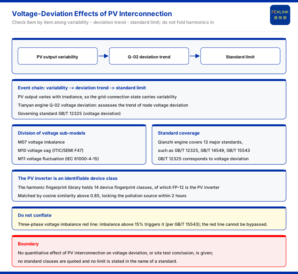
The effect of photovoltaic (PV) interconnection on voltage deviation at the grid-connection point comes from the variability of PV output. The knowledge base lists the Q-02 voltage-deviation model of the Tianyan engine / large model as one of the P0 first-release models of the power-quality block, used to assess the trend of node voltage deviation, with GB/T 12325 as its governing standard. In other words, what the knowledge base supplies for "voltage deviation after PV interconnection" is an assessment scope and a governing standard, not a test conclusion for any particular site. Interconnection impact should therefore be checked item by item along the line "variability — deviation trend — standard limit", rather than folding harmonics, imbalance, and other topics into voltage deviation and handling them as one.
Why PV interconnection moves voltage deviation
PV output tracks lighting conditions, so the output power is not constant and the operating state of the grid-connection point carries a fluctuating character. The knowledge base describes the purpose of Q-02 voltage deviation as "assessing the trend of node voltage deviation". The operative word is trend: the entry is concerned not with a single instantaneous reading but with the direction and magnitude of the deviation as interconnection conditions change. Read this way, voltage deviation is not a static index to be captured once; it belongs in a time series, and a single snapshot is not enough to characterise it. That is also why the topic is framed as trend assessment rather than as a pass/fail figure at one moment.
Assessment scope: Q-02 voltage deviation
The knowledge base records that the P0 first-release models of the Q power-quality block of the Tianyan engine / large model include Q-02 voltage deviation. This is the analysis scope used here when discussing the effect of PV interconnection: it turns the voltage state at the grid-connection point into an assessable deviation trend. As for the conditions under which PV interconnection would change the deviation, and by how much, the knowledge base gives no quantitative conclusion, and this article draws none. The scope states what is assessed and at what level of abstraction; it does not by itself predict an outcome for a given site.
Governing standard: GB/T 12325
The knowledge base records that the Qianzhi engine / large model covers 13 major standards, including GB/T 12325, GB/T 14549, and GB/T 15543, of which GB/T 12325 is the standard related to voltage deviation. This provides the standard anchor for the voltage-deviation topic. It must be emphasised that this article does not quote the clause content of GB/T 12325, and does not give limits or measurement methods under the name of the standard. Clause-level citation must first be matched within the standards library before it can be used. The standard name identifies the governing document; it is not a substitute for the clause text.
Coverage of the voltage-class sub-models
Voltage deviation is only one of the voltage-class topics. The knowledge base records that the voltage-class sub-models of the Qianzhi engine / large model include M07 voltage imbalance, M10 voltage sag (ITIC and SEMI F47), and M11 voltage fluctuation (IEC 61000-4-15). This shows that whether voltage is "steady" is characterised by a group of sub-models working together: deviation, imbalance, sag, and fluctuation each have their own scope and governing standard. The effect of PV interconnection must therefore be checked item by item; one item cannot stand in for another, and voltage deviation must not be merged with the harmonic problem into a single treatment. Treating the group as one interchangeable quantity would erase the distinctions the knowledge base keeps between the individual sub-models.
The PV inverter is an identifiable device class
PV interconnection brings not only voltage questions but possibly harmonic questions as well. The knowledge base records that the harmonic fingerprint library contains 14 device fingerprint classes, of which FP-12 is the photovoltaic inverter, matched at a cosine similarity above 0.85, and can pin down a pollution source within 2 hours. The value of this entry is that when a harmonic anomaly appears at the grid-connection point, the PV inverter can be recognised as a known class, moving the responsibility judgment onto a device class instead of leaving it at the descriptive level of "there are harmonics". Identification makes the subsequent question — which class of equipment the harmonics come from — answerable; the harmonic fingerprint library supplies exactly that step.
Monitoring and selection scope
On the device side, the knowledge base records that the power-quality monitor (ESE-22111-R) adds harmonic monitoring on top of phase monitoring, covering harmonic orders 2 through 31 at an accuracy of ±1%, and can be used for power-quality monitoring at a grid-connection point. On the analysis side, the Tianyan engine provides Q-02 voltage-deviation assessment. Separately, the knowledge base records a red-line rule for three-phase voltage imbalance: triggered when three-phase voltage imbalance is greater than 15%, with GB/T 15543 as the governing standard, and the red line cannot be bypassed. That rule is a reminder that while voltage deviation is being watched, voltage imbalance retains an independent threshold of its own; the two must not be conflated.
Selection comparison
The selection comparison table in the ninth part of the knowledge base records that for dedicated power-quality and harmonic treatment it recommends a power-quality monitor (ESE) or a multi-element electrical intelligent measurement-and-control unit (power-quality version), together with Tianyan engine harmonic analysis. Set beside Q-02 voltage deviation, this shows that a power-quality scheme for a PV grid-connection point normally has two stages: field monitoring devices and the analysis engine. The device side is responsible for measuring accurately, and the engine side is responsible for assessing. The two stages are complementary responsibilities rather than alternatives to one another.
Scope and limitations
- This article restates only what the knowledge base lists: the assessment purpose of Q-02 voltage deviation, the voltage-deviation standard anchor of GB/T 12325, the coverage of M07, M10, and M11, and the fact that FP-12 among the 14 harmonic fingerprint classes is the photovoltaic inverter. - This article gives no quantified effect of PV interconnection on voltage deviation and no test conclusion for any specific site. - Clause-level citation must be matched within the standards library before use; this article quotes no clause and gives no limit or measurement method under the name of a standard. - The red-line threshold of greater than 15% for three-phase voltage imbalance and its reliance on GB/T 15543 are limited to what the knowledge base lists, and the red line cannot be bypassed. - The selection recommendation is limited to what the selection comparison table in the ninth part lists and constitutes no selection or acceptance conclusion for any specific project.