
Direct answer
How often should the grounding grid of a traction substation be tested for grounding resistance? The product knowledge base does not give a fixed retest period. What the knowledge base does give is a method: replace single-point spot testing of the grid with online grounding-resistance monitoring units deployed at each grounding point. The knowledge base states that the FR grounding resistance monitor (FR-01311) series is applied to online monitoring of railway traction substation grounding grids, and that in a typical application scenario the recommended combination for online monitoring of substation and traction substation grounding grids is one grounding resistance monitor per grounding point, connected to the FG lightning-protection smart gateway (FG-0221-ER) and the FEXCloud IoT cloud platform. What this article can therefore answer is not "how many days between tests" but "what decides when a retest happens": the knowledge base leaves that to continuous, point-by-point online acquisition rather than writing the period as a fixed number.
How to read the model rule
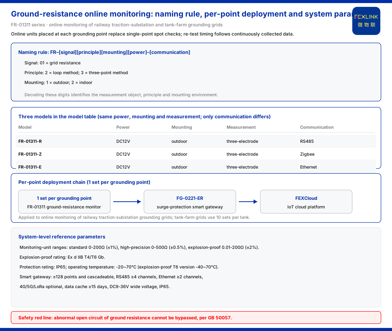
The knowledge base specifies the model rule of the grounding resistance monitor as: FR plus a signal-acquisition position, a detection-principle position, a mounting-method position, and a power-supply position, followed by a communication position. In the signal-acquisition position, 01 denotes grounding-grid resistance; in the detection-principle position, 2 denotes the loop method and 3 denotes the three-point method; in the mounting-method position, 1 denotes outdoor and 2 denotes indoor. Reading these positions makes it possible to identify the measurement object, the principle, and the installation environment of the device from the model itself.
The three models listed in the model table
The grounding resistance monitor model table in the knowledge base lists the following three models:
| Model | Power supply | Mounting | Measurement method | Communication | |:--|:--|:--|:--|:--| | FR-01311-R | DC12V | Outdoor | Three-electrode method | RS485 | | FR-01311-Z | DC12V | Outdoor | Three-electrode method | Zigbee | | FR-01311-E | DC12V | Outdoor | Three-electrode method | Ethernet |
The three models share the same power supply, mounting, and measurement method; the difference lies only in communication. In other words, this family is uniform in measurement method and mounting method, and what mainly distinguishes the models on site is the communication method.
The railway traction substation scenario
The grounding-grid application note in the product knowledge base states that the grounding resistance monitor series has been applied to online monitoring of railway traction substation grounding grids, and also to online monitoring of oil-tank-farm grounding grids (10 sets per tank). The typical application scenario table further sets out the recommended combination for online monitoring of substation and traction substation grounding grids: one grounding resistance monitor per grounding point, together with the lightning-protection smart gateway and the FEXCloud IoT cloud platform. Point-by-point deployment means that monitoring does not take a single point on the grid but acquires each key grounding point separately.
Why "online" changes the period question
The knowledge base contains no clause requiring retesting at fixed intervals; what it provides is continuous online acquisition and point-by-point deployment. In this form, operations decisions rely on the change over time of the resistance at the same grounding point, rather than on the instantaneous value of a single manual measurement. When to schedule excavation or reconstruction on that basis is an engineering judgment on the operations side, and the knowledge base does not write it as a standard clause; this article only points out that the data on which this judgment depends comes from online acquisition, and does not prescribe a specific threshold or period for a project.
System-level reference parameters
The grounding resistance monitoring unit reference ranges given in the knowledge base fall into three grades: standard type 0 to 200 ohms (±1%), high-precision type 0 to 500 ohms (±0.5%), and explosion-proof type 0.01 to 200 ohms (Ex d IIB T4/T6 Gb, ±2%). At the system level, the protection rating is IP65, the operating temperature is -20 to 70 degrees Celsius, and the explosion-proof T6 version is -40 to 70 degrees Celsius; the smart gateway can mount at least 128 points and supports cascading, with at least 4 RS485 channels and at least 2 Ethernet channels, 4G, 5G, and LoRa optional, a data buffer of at least 15 days, a DC9 to 36 volt wide-voltage supply, and an IP65 protection rating. These are system-level reference figures, and the final configuration prevails.
Red line and standard basis
The safety red-line guard table in the knowledge base lists "abnormal open circuit of grounding resistance" as a red-line rule that cannot be bypassed, and its basis standard is GB 50057. This setting indicates that the judgment on an abnormal open circuit of grounding resistance is a constraint that cannot be skipped, not an optional reference item.
Scope and limitations
- The content of this article is limited to the model rule, model table, grounding-grid application note, typical application scenarios, system-level reference parameters, and relevant entries in the safety red-line guard table for the grounding resistance monitor listed in the product knowledge base. - The knowledge base does not specify a retest period for grounding resistance, nor does it contain a clause of "how many days between tests"; this article gives no specific period value, and judgments about when to excavate or reconstruct belong to project-side engineering decisions. - The ranges, accuracies, protection ratings, operating temperatures, mounting-point counts, interface channel counts, buffer days, and supply ranges in this article are all system-level reference parameters from the knowledge base and do not constitute a commitment for a specific model or project. - The measurement method listed in the model table is the three-electrode method; the model rule separately lists the loop method and the three-point method in the detection-principle position. Both are cited as written in the knowledge base, and no inference is made about their applicable conditions. - Scenarios and application cases are limited to the industries and projects listed in the knowledge base, and no other industry applications are extended. - This article constitutes no commitment regarding any unlisted indicator; where site conditions differ from the premises above, the latest product documentation and the actual engineering solution prevail.


