
Direct answer
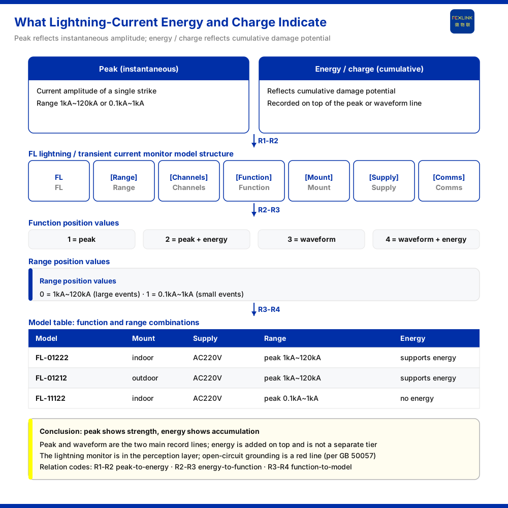
The energy parameter of a lightning current answers a class of information beyond "how strong was a single event and how did it proceed". The knowledge base divides the recording function of the FL lightning current / transient current monitor (FL-01222) into four settings: 1 peak, 2 peak plus energy, 3 waveform, 4 waveform plus energy. Two relationships can be read from this function table: peak and waveform are the two main recording lines, corresponding to intensity and process respectively; energy does not form a setting of its own but can be superimposed on either the peak line or the waveform line. Energy, peak and waveform therefore belong to different dimensions, and where energy recording is needed the function should be added on top of the chosen main line, not treated as a replacement for peak.
Peak, waveform and energy: three recording dimensions
A lightning current is a short transient process and can be separated into several points of concern. Peak concerns how strong the event was, waveform concerns the shape of its process, and energy concerns another dimension carried by the event that can be recorded alongside intensity or process. The knowledge base organises the three in one function position, showing that they are considered to require separate recording on the same device rather than replacing one another.
The distinction is practical because the three dimensions answer different operational questions. Intensity tells an operator whether the event was significant relative to the protection rating; process tells an engineer whether the surge had a shape consistent with the expected threat; energy speaks to accumulated stress that a peak alone does not capture. Any one of them, read alone, leaves part of the event unaccounted for.
Distinguishing the three matters for selection: a need to judge intensity falls on the peak line, a need to see the process falls on the waveform line, and a need for additional energy recording adds it on the corresponding main line. The function position is an independent field in the model, meaning that "how fully an event is to be recorded" is already fixed at the selection stage.
Why energy sits alongside peak and waveform
From the arrangement of the function settings, peak and waveform each occupy two settings, and energy is superimposed on these two lines rather than occupying a setting alone. This arrangement reveals the position of energy recording: it is a supplementary dimension, and adding energy only has a clear meaning after the recording of intensity or process has been decided.
Taking the models listed in the knowledge base as examples, the FL lightning current / transient current monitor comes in variants that differ in whether energy is supported:
| Model | Installation | Supply | Peak coverage | Energy support | | --- | --- | --- | --- | --- | | FL-01222 | indoor | AC220V | 1 kA~120 kA | supported | | FL-01212 | outdoor | AC220V | 1 kA~120 kA | supported | | FL-11122 | indoor | AC220V | 0.1 kA~1 kA | not supported |
Whether energy is supported is thus a dividing line between different models, and it must not be assumed that every lightning current monitor has this capability.
How the function position is set
The function position has four settings, organising the recorded content as follows: function 1 records peak; function 2 records peak plus energy; function 3 records waveform; function 4 records waveform plus energy. When reading this table, first determine the required main recording line, then decide whether to add energy. If only intensity is needed, function 1 suffices; if both intensity and energy are needed, choose function 2; if the process is the concern, choose between function 3 and function 4.
It should be emphasised that the choice of function position and the detection range are mutually independent, and together they decide what the monitor can record and up to what magnitude. Choosing only a function and ignoring magnitude, or choosing only magnitude and ignoring the function, will both cause a mismatch between configuration and requirement.
Independence is the reason the two fields must both be read. A high-magnitude model with a peak-only function records strong events without their energy; a low-magnitude model with an energy-capable function records weaker events in fuller detail. Neither field can compensate for the other, and neither can be inferred from the other.
Detection range: the magnitude boundary of energy recording
Before recording an event, the magnitude to be covered must be determined. According to the knowledge base's detection range codes, 0 is 1 kA~120 kA, for lightning current events of larger amplitude; 1 is 0.1 kA~1 kA, for transient current events of smaller amplitude. The range code appears at the start of the model, alongside the function setting.
Combining the model table shows how magnitude and function are paired: within the FL lightning current / transient current monitor family, the larger-amplitude tier (FL-01222 and FL-01212) supports energy, while the smaller-amplitude tier (FL-11122) does not. This shows that function and range are not paired arbitrarily, and the actually available combinations follow the corresponding model table.
Position in the monitoring system
From the system architecture, the knowledge base places the FL lightning current / transient current monitor in the perception layer of the monitoring system, alongside grounding resistance monitoring and surge protective device monitoring. This means lightning current recording is one class of perception-layer input; energy, peak and waveform are all raw event information acquired at this layer, and only afterwards are they organised into usable information through the edge, platform and application layers. "Whether lightning current energy needs to be recorded" is therefore a question to answer at the perception-layer selection stage.
Because this selection is made at the perception layer, it also constrains later interpretation. A function position fixed to peak alone cannot be recovered at the platform layer into a waveform record, however sophisticated the analysis above it. What the perception layer is configured to acquire sets the ceiling on everything downstream.
Applicability and limits
First, this article only explains the relationship among the three recording dimensions of peak, waveform and energy; its factual boundary is limited to the product knowledge base, and it introduces no standard clauses, parameters, certifications or cases the knowledge base does not list.
Second, the functions 1 peak / 2 peak plus energy / 3 waveform / 4 waveform plus energy, and the detection ranges 0:1 kA~120 kA and 1:0.1 kA~1 kA, are model and function definitions listed in the knowledge base.
Third, the installation method, supply and energy-support differences among the three models of the FL lightning current / transient current monitor (FL-01222, FL-01212 and FL-11122) are existing records in the knowledge base's model table; this article does not extend them to other models, nor does it make cross-tier inferences.
Fourth, the reference to GB 50057 is limited to the grounding red-line criteria recorded in the knowledge base; the article does not set out specific clauses of the standard, nor does it make a determination about the measurement results or compliance of lightning current events.


