
Direct answer
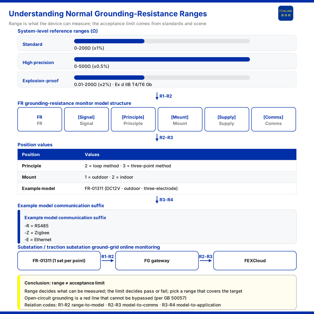
To the question "what counts as normal" for grounding resistance, two distinct ideas must be separated first: range and limit. Range is the interval of values a monitoring device can measure, answering "how wide can this device read"; a limit is the acceptance threshold set by a particular project or standard, answering "is this on-site value acceptable". In the system-level reference parameters for the grounding resistance monitoring system, the knowledge base gives ranges: standard type 0-200 Ω (±1%), high-precision type 0-500 Ω (±0.5%) and explosion-proof type 0.01-200 Ω (±2%). These are device specifications, not acceptance lines; the specific acceptance value should be determined against the applicable standard and scenario. The knowledge base also lists "abnormal open circuit of grounding resistance" as a non-bypassable red line, on the basis of GB 50057, pointing to continuous confirmation of grounding state.
Range is not a limit
Mistaking a range for a limit is the most common error when reading grounding data. A range states the device's capability boundary: if the on-site grounding resistance is above the upper end of the selected range, the reading falls outside what the device can cover and cannot simply be used as a normal value. A limit, by contrast, is a judgement criterion; it comes from the applicable requirements of a specific project, not from a device datasheet.
The relation between the two is: the limit decides what must be measured, and the range decides whether it can be measured accurately. Only if the limit falls within a given range tier does that tier have the capability to serve the monitoring requirement. At selection, then, the question is not "which range is larger" but first confirming the resistance interval that must be covered, then choosing the tier whose range matches it.
The three system-level reference ranges
The grounding resistance monitoring system-level reference ranges given by the knowledge base fall into three tiers. The standard type covers 0-200 Ω at ±1% accuracy; the high-precision type covers 0-500 Ω at ±0.5%; the explosion-proof type covers 0.01-200 Ω at ±2%, with explosion-proof rating Ex d IIB T4/T6 Gb. The three are listed side by side, showing that different scenarios place different emphasis on measurement range, accuracy and environmental adaptability.
The explosion-proof type deserves particular attention as a separate tier: it is not a routine device simply moved into a hazardous environment, but has its own dedicated range and accuracy specification. Where an explosion-proof configuration is required, the choice should come from this tier, and routine-tier parameters must not be substituted for it. The high-precision type addresses scenarios with a higher accuracy requirement and a wider resistance interval. These three are system-level reference parameters and are not equivalent to the specification of any particular model.
How the model rule carries detection principle and installation
Beyond range, the detection principle and installation method also enter the model. For the FR grounding resistance monitor (FR-01311) the knowledge base gives the rule FR–[signal acquisition][detection principle][installation][supply]–[communication]. Here detection principle 2 is the loop method and 3 is the three-point method; installation 1 is outdoor and 2 is indoor. The detection principle determines how the measurement is brought in, and the installation method determines whether the device is configured for indoor or outdoor conditions; both are fixed at the selection stage, not decided on site later.
Range landing on specific models
The knowledge base's model table lists three communication configurations of the FR grounding resistance monitor (FR-01311): the FR-01311-R, FR-01311-Z and FR-01311-E models. All three are DC12V-powered, installed outdoors and use the three-electrode method, with communication methods of RS485, Zigbee and Ethernet respectively. The same model body distinguishes the upstream method by suffix, showing that the communication field is an independent selectable item.
This also suggests a selection discipline: the fact that the model bodies share the same detection principle and installation method does not mean the communication can be assigned freely; the communication suffix must correspond to the upstream method actually available on site. Only after range, principle, installation and communication are all confirmed is the model settled.
How range enters grounding-grid online monitoring
The knowledge base lists "substation / traction substation grounding-grid online monitoring" as an application scenario, with a recommended combination of the FR grounding resistance monitor (FR-01311, one set per point) plus the lightning-protection smart gateway (FG) and platform-side service. A grounding grid is distributed as points; each point takes one monitoring unit, and the data is aggregated and uplinked through the gateway, forming a data path from the grid to the monitoring side. In this combination the range determines how wide each point can measure, while the gateway and platform aggregate the dispersed point data.
Red-line premise: abnormal open circuit of grounding resistance
The knowledge base lists "abnormal open circuit of grounding resistance" as a non-bypassable red line, on the basis of GB 50057. A red-line designation means the grounding path cannot rely on after-the-fact trend observation in place of interception; it requires continuous confirmation during operation that the state holds. This is why this article repeatedly stresses the distinction between range and limit: only when the device can read grounding resistance and read it accurately does the red-line criterion have a usable data basis.
Applicability and limits
First, this article only explains the conceptual distinction between grounding resistance range and limit; its factual boundary is limited to the product knowledge base, and it introduces no standard clauses, parameters, certifications or cases the knowledge base does not list.
Second, the 0-200 Ω (±1%), 0-500 Ω (±0.5%) and 0.01-200 Ω (±2%, Ex d IIB T4/T6 Gb) cited here are system-level reference parameters listed in the knowledge base; this article does not equate them with the specification of any particular model, nor does it use them to judge whether an on-site grounding resistance is acceptable.
Third, the reference to GB 50057 is limited to the grounding red-line criteria recorded in the knowledge base; the article does not set out specific clauses of the standard, nor does it make a determination about specific limits.
Fourth, the supply, installation method and communication method of the three communication configurations of the FR grounding resistance monitor (FR-01311-R, FR-01311-Z and FR-01311-E), and the recommended combination for "substation / traction substation grounding-grid online monitoring", are existing knowledge-base records; this article makes no cross-model inference and does not extend to quantitative effects not recorded.


