
Direct answer
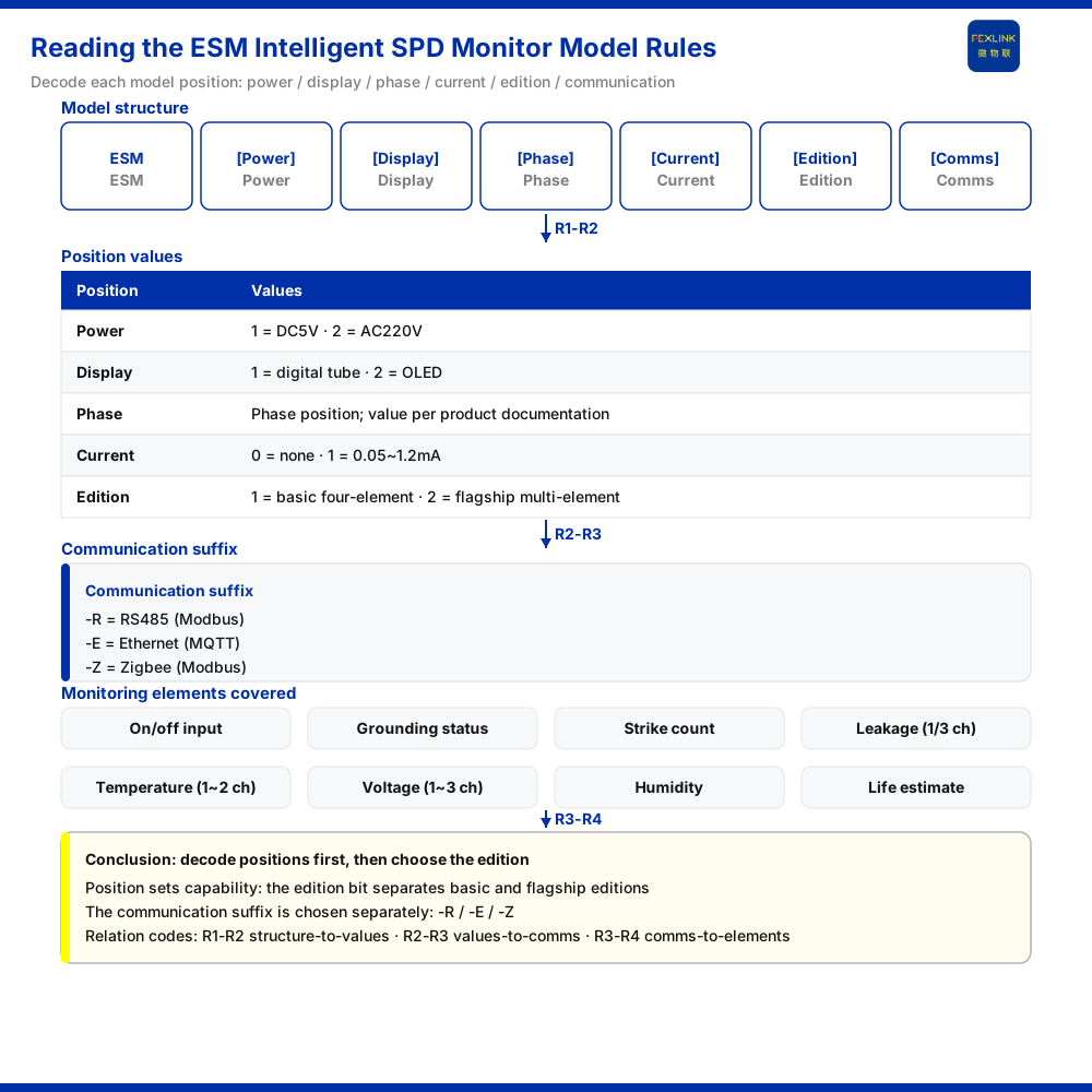
The model rule of the ESM intelligent lightning protection monitoring terminal (SPD monitor) can be read as five segments: ESM–[supply][display][phase count][current parameter][board version]–[communication]. The first four positions correspond to supply method, display method, phase configuration and current parameter; the board-version position distinguishes a basic four-element version from a flagship multi-element version; and the final segment determines how the data is delivered upward. The key to reading this rule is to treat every position as an independent choice: the same position with different codes yields a different product configuration, and the position string of one model must not be transferred directly onto another.
Overall structure of the rule
The knowledge base gives the ESM model rule as ESM–[supply][display][phase count][current parameter][board version]–[communication]. The rule fixes product features by position: the four bracketed groups in the middle stand in order, and the communication segment at the end is set apart by a dash. To read a model, first split the body from the communication at the dash, then check each bracketed position in order, and the model can be resolved into its corresponding configuration combination.
The value of a fixed-position rule is that it makes a model auditable. Any reader who knows the rule can take a model string, split it and reconstruct the exact set of choices the product encodes; two readers arrive at the same reading without relying on memory or on a sales description. This is why the bracketed order matters, and why the rule should be read as a specification rather than as a naming style.
The first four positions: supply, display, phase count and current parameter
According to the knowledge base's value descriptions, the position codes mean the following. Supply: 1 is DC5V, 2 is AC220V. Display: 1 is a digital tube, 2 is OLED. Current parameter: 0 is none, 1 is 0.05~1.2 mA. The phase-count and current-parameter positions together determine the terminal's access scale for loop-current information.
Read together, these positions show that the rule first answers "how is it powered and how does it display", then "what current quantity does it connect to". Supply and display are the device's own operating conditions, while the current parameter is a monitored object; the three occupy their own positions in the model and do not stand in for one another. The two conditions are not interchangeable: a model with the higher supply code does not thereby gain display or current capability, and a model with a display code does not thereby gain a current channel. Each position answers its own question, and the answer to one position says nothing about the others. Note especially that a current-parameter position of 0 means the item is not configured; "supports 0.05~1.2 mA" must not be assumed by default for any product that does not carry a current-parameter position.
The board-version position: basic four-element and flagship multi-element
The board-version position is the most semantically meaningful segment of the rule: 1 is the basic four-element version, 2 is the flagship multi-element version. The two versions differ not in appearance but in the coverage of monitored elements. The basic four-element version targets a fixed set of core elements; the flagship multi-element version covers more elements on that basis.
In its model parameter table the knowledge base lists the monitoring elements ESM can cover, including switching quantities, grounding status, strike count, leakage current (1 or 3 channels), temperature (1~2 channels), voltage (1~3 channels), humidity and lifetime estimation. The channel count of an element is given in brackets, showing that the same element may also differ in the number of channels. At selection, therefore, the board version and the element list must be checked together: first establish which elements the project needs, then judge whether that configuration falls within the coverage of the chosen board version.
This is where the most consequential selection error sits: assuming that the flagship version is simply "the same product with more" and that any element in the list is therefore available. The list describes what ESM as a series can cover; the board version describes how much of that coverage a specific unit carries. The two must be matched against the requirement, not assumed from the label.
The communication segment: three common suffixes
The communication method in the final segment follows the knowledge base's common-suffix convention: -R is RS485 (Modbus), -E is Ethernet (MQTT) and -Z is Zigbee (Modbus). The three suffixes correspond to three upstream forms, suited respectively to a wired bus, Ethernet and wireless networking. The communication segment is the position that maps directly to the on-site network condition; selection should proceed from the upstream method available on site, not from a model chosen first and a network bent to fit it.
The suffix is not a preference but a constraint. A site whose only viable path is a wired bus cannot use a wireless-suffix product simply because the rest of the model is a good fit; conversely, a site with no wired infrastructure should not be specified with a wired suffix and left to solve connectivity later. Reading the last segment first, as a filter, is often faster than fitting it last.
How the model rule lands in selection
Putting the segments together, selection can proceed in one order: first fix the supply position according to on-site supply, then the display position according to display needs, then the current-parameter position according to the current quantity to be monitored, then the board version according to the element list, and finally the communication suffix according to the on-site upstream condition. The knowledge base lists "surge protective device status monitoring (retrofit of existing SPDs)" as an application scenario, and the recommended combination includes full-element SPD monitoring with ESM, showing that under a full-element monitoring requirement ESM corresponds to a class of terminal with relatively complete element coverage.
The order is deliberate: capability before connectivity. Deciding quantity and board version first fixes what the terminal must do; deciding communication last fixes how that capability leaves the site. Reversing the two tends to produce a configured terminal that cannot be reached, or a reachable terminal that measures the wrong set of quantities.
Applicability and limits
First, the reading of the ESM model rule in this article is limited to the model rule and value descriptions in the product knowledge base, and does not add models, protocol details, certifications or engineering cases the knowledge base does not list.
Second, the supply 1:DC5V / 2:AC220V, display 1:digital tube / 2:OLED, current parameter 0:none / 1:0.05~1.2 mA, board version 1:basic four-element / 2:flagship multi-element, and the meanings of the communication suffixes -R / -E / -Z are all existing knowledge-base records; this article does not extend them to other models or other protocols.
Third, the channel counts in the monitored-element list (leakage current 1/3 channels, temperature 1~2 channels, voltage 1~3 channels) are as listed in the knowledge base; which elements and channel counts a particular model covers should follow the corresponding model table, and this article makes no cross-model inference.
Fourth, this article does not present any specific configuration combination as a certification or compliance conclusion; actual selection should be confirmed against on-site supply, network conditions, the element list and the corresponding model table.


