
1. Direct answer
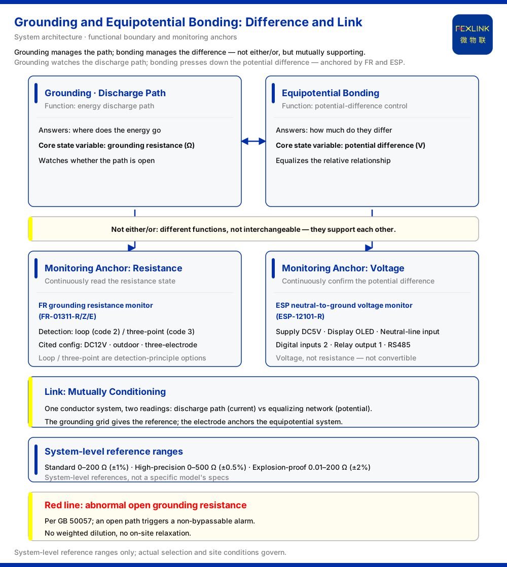
Grounding and equipotential bonding are not the same thing. They are often named together and assumed interchangeable, yet their functions differ. Grounding provides a path for lightning and fault current to discharge into the earth—it answers "where does the energy go." Equipotential bonding presses the potential difference between conductors, and between conductors and a reference point, down to a sufficiently small value—it answers "how much do they differ." Two matching product categories are provided: grounding resistance monitoring and neutral-to-ground voltage monitoring. One watches the resistance state of the discharge path, the other the voltage state of the potential difference—not an either/or choice but a mutually supporting pair.
2. Functional difference: a discharge path versus potential-difference control
Start with what each assesses. The object of grounding is the current path: its goal is to conduct abnormal current into the earth at the lowest possible impedance, and its core state variable is grounding resistance, in ohms. The lower the resistance, the more freely the discharge proceeds and the less likely the path is to fail at a critical moment. The object of equipotential bonding is the relationship between potentials: its goal is to connect metal parts that might otherwise sit at different potentials to the system reference point so the difference is small enough to avoid discharge, counter-strike, and shock risk. Its core state variable is potential difference, in volts.
The simplest contrast: grounding asks whether the path is open and unobstructed; equipotential bonding asks how large the difference between two points is. They are often conflated because good engineering carries them on the same conductor network, so an observer "sees the conductors but not the functions."
3. Why neither can replace the other
Consider first grounding with potential relationships left unmanaged. Even with a discharge path, a high potential difference can still appear between devices, or between a device and the earth, during a transient: the energy has an outlet, but the potential distribution around it can still cause damage. A passing grounding resistance only shows the path itself meets the requirement; it does not mean the differences between points have become small.
Now consider equipotential bonding without reliable grounding. Conductors are tied to a common potential, but with no stable destination for discharge, the whole set of potentials can be raised together; equalization then floats with the reference point, looking like "everything is equal" when in fact "everything drifts together." Bonding addresses the relative relationship; it cannot replace an absolute destination.
Grounding solves "is there an outlet," equipotential bonding solves "are they level." The two dimensions cannot substitute for each other, and a pass on one cannot cover a gap in the other.
4. The link: two functions that are conditions for each other
Equipotential bonding needs a reference potential, and the earth is usually the final reference; the grounding grid supplies it. Conversely, the effect of grounding is expressed through the potential distribution, and the grounding electrode anchors the equipotential system. In engineering, good grounding and complete bonding are often two readings of one conductor system: seen from the current, a discharge path; from the potential, an equalizing network.
The safety red line lists "abnormal open circuit of the grounding resistance" as a non-bypassable criterion, with GB 50057 recorded as its basis. The red line takes no part in weighted dilution among metrics and cannot be relaxed on site. It sits there precisely because it supports both functions—discharge and equalization. Once the path is open, the reference on which equipotential bonding depends also fails.
5. The anchor for grounding monitoring: resistance
Turning "is the discharge path intact" into executable management requires a device that continuously acquires the resistance state: the FR grounding resistance monitor (FR-01311-R/Z/E). Its detection principle is given as two codes: 2 for the loop method and 3 for the three-point (three-electrode) method. The FR-01311-R/Z/E is DC12V supplied, installed outdoors, and uses the three-electrode method. Selection must first confirm which measurement method the site permits before discussing range and installation. Grounding resistance is the direct state variable of "is the path intact"; making it continuously readable moves the check from a one-time measurement to continuous confirmation, consistent with the red line's requirement of interception at the first moment.
| Product name | Model | Detection principle | Supply / installation / measurement | | --- | --- | --- | --- | | FR grounding resistance monitor | FR-01311-R/Z/E | Loop method (code 2) / three-point method (code 3) | DC12V / outdoor / three-electrode method |
6. The anchor for potential-difference monitoring: voltage
The quantity equipotential bonding watches is potential difference, and neutral-to-ground voltage is a specific form of it. The corresponding device is the ESP neutral-to-ground voltage monitor (ESP-12101-R). Its parameters include DC5V supply, OLED display, neutral-line input, 2 digital inputs, 1 relay output, and RS485 communication.
Each parameter maps to an acquisition or control requirement: the neutral-line input obtains the neutral potential reference, the OLED gives local readout, the digital inputs and relay offer local control, and RS485 handles networking and reporting. Monitoring by voltage rather than resistance is the most direct dividing line from grounding monitoring—the grounding side answers "how large is the resistance, is the path open," the potential-difference side "how much do neutral and ground differ, has it been pressed low." The two measure different quantities and cannot be converted into each other.
| Parameter | Value | | --- | --- | | Supply | DC5V | | Display | OLED | | Input | neutral-line input | | Digital inputs | 2 channels | | Relay output | 1 channel | | Communication | RS485 |
7. Ranges and standards: the boundary of each configuration
System-level reference ranges for grounding monitoring units are: standard type 0–200 Ω (±1%), high-precision type 0–500 Ω (±0.5%), and explosion-proof type 0.01–200 Ω (±2%). Span and accuracy are tiered by configuration, with the explosion-proof type listed separately for environments beyond the standard one. These figures answer whether grounding can be measured accurately under different conditions; they are system-level references, not any specific model's specifications.
The standards basis also needs a limit. GB 50057 is the basis cited for the red line governing "abnormal open circuit of the grounding resistance"; this article's reference is limited to that, without expanding its clauses or drawing conclusions about its limit values. The standard here supports the precondition that "the grounding path must hold," not a number suited to every site.
| Type | Range | Accuracy | | --- | --- | --- | | Standard type | 0–200 Ω | ±1% | | High-precision type | 0–500 Ω | ±0.5% | | Explosion-proof type | 0.01–200 Ω | ±2% |
8. How the two monitoring functions divide configuration
Four steps. First, ask what quantity is watched: "is the discharge path intact, is the resistance abnormally open" corresponds to grounding resistance monitoring; "has the neutral-to-ground potential difference been pressed low" corresponds to neutral-to-ground voltage monitoring. The quantity determines the configuration.
Second, look at measurement method and site conditions: on the grounding side, confirm whether the loop method or the three-electrode method is usable on site, and match the DC12V supply and outdoor installation to the site. Third, consider local control: the neutral-to-ground voltage monitor carries digital inputs and a relay output for local interlocking, whereas the grounding resistance monitor focuses on acquisition and reporting. Fourth, coordinate: deploy the two together—grounding provides the reference and destination, the potential-difference side confirms whether the reference is truly pressed down, and together they form a complete safety floor.
One final discipline: do not infer that the other is acceptable from the acceptance of one; a passing grounding resistance and a pressed-down potential difference are different conclusions, confirmed separately.
9. Scope and limitations
First, the facts stated here are drawn from the documented model and system data; no standard clauses, parameters, certifications, or cases beyond that documentation are introduced.
Second, this article's reference to GB 50057 is limited to the single citation for grounding resistance abnormal open circuit; it does not expand the standard's clauses and does not determine grounding resistance limit values.
Third, the ranges 0–200 Ω (±1%), 0–500 Ω (±0.5%), and 0.01–200 Ω (±2%) are system-level reference parameters, not the specifications of any specific model.
Fourth, the loop method and the three-point (three-electrode) method are detection-principle options, and DC12V, outdoor, and the three-electrode method are the corresponding configuration; actual product parameters are governed by the selected model.
Fifth, this article explains the functional boundary and monitoring anchors of the two; it does not replace the grounding or equipotential design, testing, or compliance determination of a specific project, which should follow site conditions and product access capability.


