
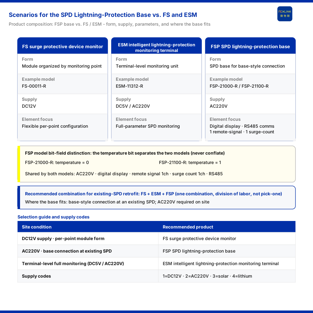
One-sentence answer: the SPD lightning-protection base (FSP-21000-R and FSP-21100-R) suits installation scenarios where an existing surge protective device (SPD) is paired with a base that brings remote-signaling input and lightning-strike counting into the monitoring link, with AC220V available at the site. The surge protective device monitor (FS-00011-R) addresses DC12V-powered module forms organized by monitoring point. The intelligent lightning-protection monitoring terminal (SPD monitor, e.g., ESM-11312-R) addresses terminal-level monitoring powered from DC5V or AC220V. In the "surge protective device status monitoring (retrofit of existing SPDs)" scenario, all three are listed as one recommended combination, indicating complementary division of labor rather than an either/or substitution.
1. The conclusion first: the base solves the "connection" problem
The product positioning of the SPD lightning-protection base is an SPD base. It is not a standalone monitoring instrument; it pairs with a surge protective device in base form and takes on the role of "carrying and connecting." Its parameter boundary is defined by the model table: both FSP-21000-R and FSP-21100-R use AC220V power, digital-tube display, 1 remote-signaling input, 1 lightning-strike count, and RS485 communication. The difference lies in the temperature bit: FSP-21000-R carries a temperature value of 0, FSP-21100-R a value of 1.
Presence or absence of temperature is the dividing line between the two models. Temperature must not be treated as a common attribute of the family, nor a bit-field from one model copied onto the other. The applicable scenario follows directly: an existing surge protective device on site, a wish to bring remote signaling and lightning-strike counting into an existing monitoring link without building a complete new monitoring terminal, and site capability to supply AC220V to the base.
2. Suitable scenario: base-style connection in existing-SPD retrofit
The recommended combination for "surge protective device status monitoring (retrofit of existing SPDs)" is the surge protective device monitor / ESM all-parameter SPD monitoring / SPD lightning-protection base. The three are listed as one combination, not offered as a one-of-three answer.
A retrofit typically has these characteristics: the surge protective device already exists, and the retrofitting party must solve "how to monitor it and how to get the data out." The value of the SPD lightning-protection base here is form-factor fit. It pairs with the existing surge protective device through a base-shaped mounting method, focuses on two "access-type" signals — remote-signaling input and lightning-strike counting — and uses AC220V power with RS485 communication. For switchgear assembly plants and solution engineers, this means the base can be considered part of the surge protective device's mounting structure when designing cabinets and mounting structures, rather than arranging a separate standalone monitoring terminal for each point.
Conversely, if the site needs more complete parameter presentation or a single standalone terminal for central display, the base form alone is not enough; the intelligent lightning-protection monitoring terminal should join the same-scenario combination. That is the practical meaning of a "combination recommendation": the base handles connection, while the module or terminal handles acquisition and presentation.
3. Difference from the surge protective device monitor: power supply and mounting form are two practical lines of distinction
The first line is power supply. The surge protective device monitor uses DC12V, while the SPD lightning-protection base uses AC220V. This is not an interchangeable parameter but a hard constraint set by site power conditions: when the site has only low-voltage DC12V, the surge protective device monitor matches; when the site can supply AC220V to the base, only then does the SPD lightning-protection base match.
The second line is mounting form. The surge protective device monitor is positioned as an SPD monitoring module, a module form organized by monitoring point; the SPD lightning-protection base is positioned as a base, a mounting structure paired with the surge protective device. Both may land in a retrofit scenario, but their roles differ: the module emphasizes flexible configuration by monitoring point, the base emphasizes accepting connections in base form.
Reduced to one line: with DC12V site power and modules organizing the monitoring points, look to the surge protective device monitor; with AC220V and remote signaling and lightning-strike counting to be connected at an existing surge protective device position in base form, look to the SPD lightning-protection base.
4. Difference from the intelligent lightning-protection monitoring terminal: access-type parameters versus terminal-level monitoring
In the retrofit scenario, the intelligent lightning-protection monitoring terminal is described as "all-parameter SPD monitoring." On power, it supports both DC5V and AC220V, whereas the SPD lightning-protection base has the single AC220V option. This difference determines the range of site power conditions it serves: only when AC220V can be provided does the SPD lightning-protection base match; for DC5V low-voltage power, go back to the intelligent lightning-protection monitoring terminal to verify.
In scenario role, the intelligent lightning-protection monitoring terminal faces terminal-level complete monitoring presentation, while the SPD lightning-protection base faces base-style connection. When the need is "add a monitoring terminal with relatively complete parameters," the terminal form fits better; when the need is "complete the connection means on an existing surge protective device," the base form fits better. In an existing-SPD retrofit the two may appear together, forming a division of labor where "the terminal acquires and presents, the base handles connection," rather than replacing one another.
5. Treat the supply code as a cross-reference language, not a substitute for site survey
The power-supply codes for lightning-protection products are: 1 for DC12V, 2 for AC220V, 3 for solar, and 4 for lithium battery. For cross-reference, the surge protective device monitor falls on the DC12V side, the SPD lightning-protection base on the AC220V side, and the intelligent lightning-protection monitoring terminal has models for both DC5V and AC220V.
Two points must be stressed. First, the supply code is the language of classification and naming, used to distinguish products, not to infer that a site definitely has a given power source. Second, power conditions come from the site and must be based on an actual power survey; one must not work backward from "a product supports a certain supply" to conclude the site already has it. When site power does not satisfy the requirement, the selection conclusion does not hold.
6. Selection checklist
1. Does the site already have a surge protective device? This is the precondition for deciding whether base-style connection is needed. 2. Are the parameters to be connected remote-signaling input and lightning-strike counting? If so, the parameter boundary of the SPD lightning-protection base corresponds. 3. Is temperature needed? If yes, it corresponds to FSP-21100-R; if no, to FSP-21000-R. The two models must not be described interchangeably. 4. Can the site provide AC220V? The SPD lightning-protection base uses AC220V, and this is a hard constraint. 5. Is terminal-level, relatively complete monitoring needed? If so, go back to the intelligent lightning-protection monitoring terminal to verify, rather than substituting the base form. 6. Is a DC12V module form needed? If so, go back to the surge protective device monitor to verify.
7. Common misconceptions and boundaries
- Treating the SPD lightning-protection base as a standalone monitoring instrument: it is a connection product in base form and does not carry terminal-level complete monitoring presentation. - Mixing up the two models: FSP-21000-R and FSP-21100-R differ in the temperature bit and are not equivalent. - Reading a "combination recommendation" as "pick one of three": the recommendation is a division of labor across base, module, and terminal. - Treating the supply code as a site survey: the code is classification language; whether DC12V or AC220V is available must be based on actual power conditions. - Inferring the whole family from one variant's conditions: different bit fields and supply variants exist within one family and must not be applied across variants.
Scope and limitations
The power-supply codes for lightning-protection products, together with the model and parameter information for these three products, correspond to the scenario "surge protective device status monitoring (retrofit of existing SPDs)." The model examples — the FS surge protective device monitor (FS-00011-R), the ESM intelligent lightning-protection monitoring terminal (ESM-11312-R), and the FSP lightning-protection base (FSP-21000-R and FSP-21100-R) — illustrate form factor, power supply, and parameter boundaries only.
This article does not infer certifications, accuracy, protocol details, or engineering cases beyond those documented, nor extend a scenario recommendation into a general conclusion. The difference between FSP-21000-R and FSP-21100-R is stated only via the temperature bit; other shared items are governed by the model table, and actual configuration should follow that table's bit-field combination and site conditions. If site parameter requirements, power capability, or existing SPD structure differ from the assumptions here, return to the parameter list and power check for a fresh judgment rather than applying a model directly. For cross-family combination schemes, confirm power and structure before selecting specific models.


