
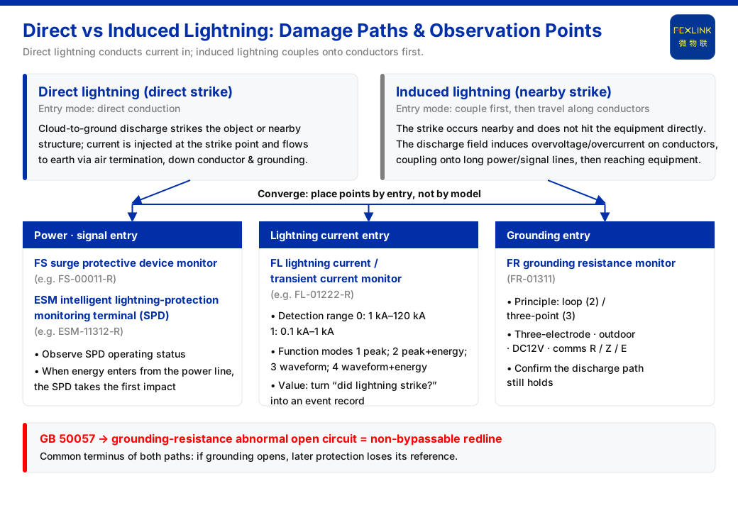
**Direct answer**: the difference between direct and induced lightning is not which equipment gets damaged but which entry the energy uses to enter the system. Lightning-protection monitoring elements include power-supply voltage, SPD status, grounding, and lightning-strike count, showing that lightning energy can enter along power lines, signal lines, and the grounding grid by several paths. Monitoring must therefore cover those entries, not fix on the equipment end alone. This article first clarifies how the two paths arise, then works down to entries, observation, and deployment.
1. Two Kinds of Lightning Differ in "How They Get In"
Direct lightning is a cloud-to-ground discharge that strikes the protected object or a nearby structure directly. Energy enters as current at the strike point and discharges to earth along the air-termination, down-conductor, and grounding path; equipment, cables, and structures on that path bear the lightning current conducted in directly.
Induced lightning is different: the strike occurs nearby without hitting the equipment directly, and the electromagnetic field change of the discharge induces overvoltage and overcurrent on conductors. It may come from electrostatic or electromagnetic induction, and typically appears on longer power and signal lines.
The key difference is the mode of entry. Direct lightning pours current straight into the struck object; induced lightning first couples energy onto a conductor, which then carries it to the equipment. For protection and monitoring this matters more than magnitude, because it determines which path must be watched.
A boundary must be drawn: the above is a general engineering distinction between the two causes; no physical parameters for them are asserted here, and this article does not infer any.
2. Different Paths, but the Entries Converge
Whether direct or induced, energy can only damage equipment by entering through some entry. Engineering commonly groups these into three: power entry, signal entry, and grounding entry. Power and signal lines are both the main carriers of induced-lightning coupling and possibly part of direct-lightning conduction; the grounding grid is the common terminus of discharge.
Because the entries converge, deploying monitoring points by equipment model alone misses the upstream. The equipment end often sees only the result; the upstream of the path determines where the energy came from and whether it was intercepted. This separates the topic from a general product introduction: first recognize the path, then discuss where monitoring points belong.
3. How the Entries Are Observed
The monitoring system uses a four-layer architecture of perception, edge, platform, and application layers. Its perception layer lists monitoring modules, smart meters, and sensors such as Rogowski coils, NTC, and microamp-level leakage-current sensors. These objects sit in different locations and correspond to different entries.
Take the power entry. The FS surge protective device monitor (e.g., FS-00011-R) and the ESM intelligent lightning-protection monitoring terminal (SPD monitor, e.g., ESM-11312-R) focus on the working state of the surge protective device. When lightning energy comes in along the power line, the surge protective device is the first link to bear the impact, and whether its state holds determines whether the energy was discharged. Observing the power entry is thus essentially observing "whether the discharge link is still usable".
The lightning current itself requires an instrument that records strike events; the grounding entry requires means that continuously reflect grounding state. These two are treated separately below.
4. The Lightning-Current Entry: Turning "Did Lightning Arrive" into an Event Record
The FL lightning current / transient current monitor (e.g., FL-01222-R) has two detection ranges: range 0 is 1 kA–120 kA, range 1 is 0.1 kA–1 kA; the function ranges are peak (1), peak + energy (2), waveform (3), and waveform + energy (4).
These two groups answer different questions. The detection range decides "how large a current can be measured"; the function range decides "whether peak, energy, or waveform is recorded". Because direct and induced lightning enter differently, the current at different entries also differs; range and function range give room to choose by site conditions. Selection should follow "what question the site most needs answered", not a default that a higher grade is better. Specific values and grade correspondence are subject to site survey and the applicable ranges; this article does not infer that any grade maps to a particular lightning type.
For deployment, the value of this entry is that it records the energy event entering the system, so one can check "whether a given strike really reached this path" rather than reconstructing it from the equipment end's symptoms alone.
5. The Grounding Entry: The Common Terminus of Both Paths
The FR grounding resistance monitor (FR-01311) has detection principles including the loop method (2) and the three-point method (3); this model uses the three-electrode method, installs outdoors, is powered at DC12V, and comes in R, Z, and E versions by communication method.
Why discuss grounding specifically here? Because whether it is discharge of direct-lightning current or of induced overvoltage, grounding is the common reference and final outlet. Once grounding becomes abnormal, both paths lose their last safeguard at once. Grounding is not an accessory indicator of one device; it is a precondition both kinds of lightning depend on.
The grounding entry therefore observes "state" rather than "event": it does not record how many strikes occurred but continuously confirms whether the discharge path still holds. This complements the event-style recording of the lightning-current entry, and the two should not substitute for each other.
6. Why the Standard Settles on "Grounding Resistance Abnormally Open"
The safety red line, based on GB 50057, marks "grounding resistance abnormally open" as a criterion that cannot be bypassed and whose threshold no one can raise.
The reason is clear: among many observable quantities it picks the class that is "decidable in state and unacceptable in consequence". An open grounding is not a gradual trend but a question of whether the safety path holds — once grounding breaks, all later protection loses its reference. Because it admits no compromise, it suits a non-bypassable setting without comparison against other indicators.
The relationship between GB 50057 and monitoring compresses to one sentence: turn the standard's requirement on grounding into "grounding state observable, abnormality non-bypassable". This is the convergence point of the two damage paths in the monitoring system.
7. What This Means for Protection and Monitoring
First, deploy by entry, not by a model list. One device may sit on several paths, but what decides whether protection holds is the upstream entry; entry first, equipment second, so the list does not hide the problem.
Second, all three entries need observation; miss one and a blind spot appears. Measuring only the equipment end leaves the upstream to luck: where energy came in and whether it was intercepted cannot be stated.
Third, protection and monitoring are a pair. The surge protective device discharges; monitoring confirms whether it was triggered and whether grounding holds. With a discharge action but no state observation, effectiveness cannot be proven.
Returning to the opening question: direct and induced lightning have different damage paths, and the direct implication for monitoring is that points must cover the power, signal, and grounding entries rather than only the equipment end.
8. Three Common Misjudgments
First, treating induced lightning as a "smaller version of direct lightning" and comparing magnitude only. The two enter differently; induced lightning couples energy onto conductors before it reaches equipment, so a bare size comparison overlooks its propagation path.
Second, monitoring only the equipment end and treating an alarm as the whole picture. The equipment end sees the result; the upstream entry is where energy actually came in.
Third, assuming that fitting a surge protective device completes protection. It needs a usable grounding as its outlet; if this common precondition fails, discharge cannot be discussed.
Scope and Limits
First, references to GB 50057 are limited to the single point where the safety red line marks "grounding resistance abnormally open" as a criterion, and do not cite other clauses.
Second, the direct/induced distinction is general engineering knowledge used to explain the path difference; no physical parameters for the two are asserted, and this article infers no magnitude, waveform, probability, or other numeric value.
Third, the detection ranges of the FL lightning current / transient current monitor (range 0: 1 kA–120 kA; range 1: 0.1 kA–1 kA) and its function ranges (peak, peak + energy, waveform, waveform + energy) are limited to the stated model ranges; no correspondence between a grade and a specific lightning type is inferred.
Fourth, the loop and three-point methods of the FR grounding resistance monitor, and the three-electrode method, outdoor installation, DC12V supply, and R/Z/E versions of FR-01311, are limited to the stated model ranges; no other models or parameter ranges are inferred.
Fifth, this article does not address grounding-resistance limits, lightning-protection levels, or acceptance conclusions for any specific project; implementation still requires review against site survey and applicable standards.


