Direct answer
Measure first, compensate second. When the power factor is low, the starting point is not to buy and install a capacitor bank, but to first obtain a clear picture of power factor, harmonics, and phase data, complete harmonic and resonance verification, and only then determine compensation capacity and method. "Install a capacitor bank first or investigate harmonics and load composition first" is not an either/or choice: investigating harmonics and load composition is a precondition of the compensation plan, while installing compensation equipment is an execution step. Without harmonic and resonance verification before compensation, a blind investment in capacitors may, under a harmonic-rich background, form a resonant circuit that turns a measure meant to cut losses into one that amplifies harmonics and endangers equipment.
1. Why "compensation equals loss reduction" is incomplete
Equating power factor compensation directly with loss reduction assumes the distribution system is dominated by power-frequency, linear loads with negligible harmonics. Under that premise, the capacitor's reactive power cancels inductive reactive power, the power factor rises, and line current and losses fall; the logic holds. But industrial and commercial sites often do not satisfy this premise: non-linear loads such as rectifiers, variable-frequency drives, UPS systems, charging piles, and photovoltaic inverters inject harmonics. Once harmonics reach a certain level, a resonant condition may form between the capacitor and the system inductance.
The Wanxiang engine's cross-dimension correlation rules state this risk plainly: VOLT-012 notes that "high harmonics + reactive power compensation switched in → resonance risk," and PQ-001 notes that "THD and power factor deteriorate in step → harmonics interfere with reactive power." Together they show that harmonics and reactive power are an entangled pair that cannot be handled separately. When a low power factor is accompanied by high harmonics, deciding from the power factor alone skips the risk judgment. "Compensation equals loss reduction" should therefore be corrected to: harmonic and resonance verification must precede compensation. Compensation itself is not the goal; whether the compensated system is safer and whether line losses actually fall are the meaningful criteria.
2. The starting point is measurement: two data sets
The starting point of reactive power compensation optimization is data, not equipment. According to the knowledge base, the Qianzhi engine's power factor sub-model (M09) handles power factor measurement and belongs to the power-quality health-check direction; the ESE power-quality monitor (e.g., ESE-22111-R to ESE-22161-R) provides both harmonic and phase monitoring, supplying data for pre-compensation verification.
The first data set is power factor. It answers "what is the system's current overall reactive power level" and indicates whether compensation is needed and the direction of its magnitude. But power factor is a composite result: it does not distinguish the causes of reactive power or reflect whether a harmonic background exists. Setting capacity from a single power factor value treats a result as the whole information set.
The second data set is harmonics and phase. Harmonic data (THD and the distribution of individual orders) answers "whether harmonics exist and to what degree," while phase data helps determine the nature and direction of reactive power flow. Only with both can one judge whether the low power factor is caused purely by inductive loads or by a reactive power problem superimposed on harmonics. The two cases differ: the former can be compensated directly per reactive power demand; the latter must first address harmonic and resonance verification before capacity and method are discussed. In short, "using power factor and harmonic data to determine compensation capacity and method" is the core method of compensation optimization; without sufficient data, capacity and method cannot be discussed at all.
3. Load composition determines the compensation method
On the same bus, different load compositions mean different natures of reactive power and different suitable compensation methods. For circuits dominated by power-frequency inductive loads, reactive power is relatively stable and the method choice is clear. For circuits dominated by non-linear loads with high harmonic content, reactive power and harmonics are superimposed, and the method must account for both harmonic withstand and resonance avoidance. Load composition is therefore not background information; it is a key input determining the compensation method.
In sequence, load composition should be investigated in parallel with harmonic measurement and before capacity and method are determined. If verified only after equipment is installed, a site found unsuitable for direct conventional capacitor compensation may face rework or introduce resonance risk in operation.
The knowledge base does not elaborate the algorithm parameters or setting rules of the reactive power compensation optimization model (C-01). This article therefore discusses only the starting point, sequence, and criteria, giving no specific capacity calculation method, setting parameter, or selection conclusion.
4. Verification sequence: why harmonics and resonance come first
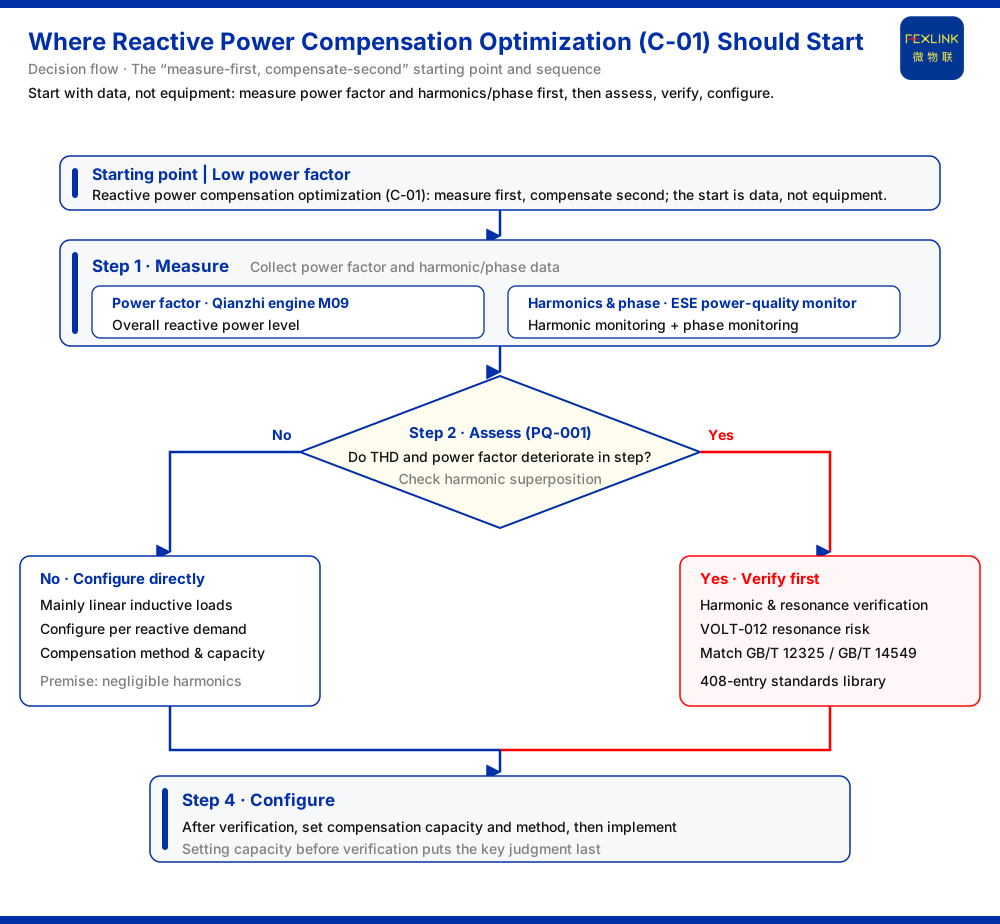
The sequence can be summarized in four steps: measure, assess, verify, configure.
The first step is measurement, collecting power factor, harmonic, and phase data.
The second step is assessment: check whether THD and power factor deteriorate in step (corresponding to PQ-001), and judge whether the site meets the precondition for resonance risk, namely "high harmonics" (corresponding to VOLT-012). This reduces "low power factor" to the judgment of whether a harmonic problem is superimposed.
The third step is verification. After the harmonic background is clarified, perform harmonic and resonance verification and match the corresponding standard clauses. According to the knowledge base, the requirements related to voltage deviation and harmonics correspond to GB/T 12325 and GB/T 14549 respectively, and their specific clauses must be matched in the standards engine's 408-entry standards library. Compliance criteria thus come from clause matching in the standards library, not from values set by experience.
The fourth step is configuration, and only then: after measurement, assessment, and verification, determine compensation capacity and method, and select equipment accordingly.
Resonance verification must precede configuration because it answers "whether compensation can be done and in what way," not "how much to compensate." If high harmonics exist, conventional capacitor compensation itself may be a source of risk; the method choice is then more critical than the capacity number. Setting capacity first and verifying afterwards puts the most important judgment last.
5. Why these two rules are warnings
PQ-001 and VOLT-012 deserve repeated reference because they describe not equipment failures but failure modes at the plan level. Resonance after compensation is switched in is often not substandard equipment, but a plan that failed to incorporate harmonic conditions when it was formulated. The cost is systemic: resonance amplifies harmonic currents at specific orders and affects the capacitor itself as well as other equipment on the same bus, so its scope may extend beyond the compensation circuit. Placing the two rules at the entrance of the compensation decision first rules out "plan-level errors" before equipment-level configuration. The cost of measurement and verification is usually far lower than a single rework and shutdown caused by resonance.
6. Starting-point summary
Back to the original question: when the power factor is low, add a capacitor bank first, or investigate harmonics and load composition first?
The answer is to investigate first. Specifically:
- Measure the power factor first (Qianzhi engine power factor sub-model M09). - Measure harmonics and phase at the same time (ESE power-quality monitor) to establish the harmonic background. - Use PQ-001 and VOLT-012 to assess whether harmonics and reactive power are superimposed and whether the precondition for resonance exists. - Perform harmonic and resonance verification, and match clauses in the 408-entry standards library in accordance with GB/T 12325 and GB/T 14549. - Only at the end determine compensation capacity and method, and implement compensation.
This path restores "compensation" from a one-time procurement action into a plan decision premised on data and constrained by verification.
Scope and limitations
This article discusses only the starting point, data basis, and verification sequence of reactive power compensation optimization. Its scope is limited to the reactive power compensation optimization model (C-01) in the energy-saving measures C section of the Tianyan engine in the knowledge base, the Qianzhi engine power factor sub-model (M09), the Wanxiang engine correlation rules PQ-001 and VOLT-012, the harmonic and phase monitoring entries of the ESE power-quality monitor, and the statement that GB/T 12325 and GB/T 14549 must be matched through the 408-entry standards library.
It answers "where to start"; it does not conclude on compensation capacity, method, or setting parameters for any specific site. The knowledge base does not elaborate the algorithm parameters or setting rules of the reactive power compensation optimization model, so this article gives no capacity calculation, setting values, or selection recommendations, nor any guarantee of any equipment's compensation effect. The applicable clauses of the standards mentioned are subject to the matching results of the standards engine's 408-entry standards library, and no specific limits are listed. For on-site implementation, measured power factor, harmonic and phase data, load composition, and standard clause matching results should be checked item by item; this sequence framework must not be applied directly as a specific parameter conclusion.