
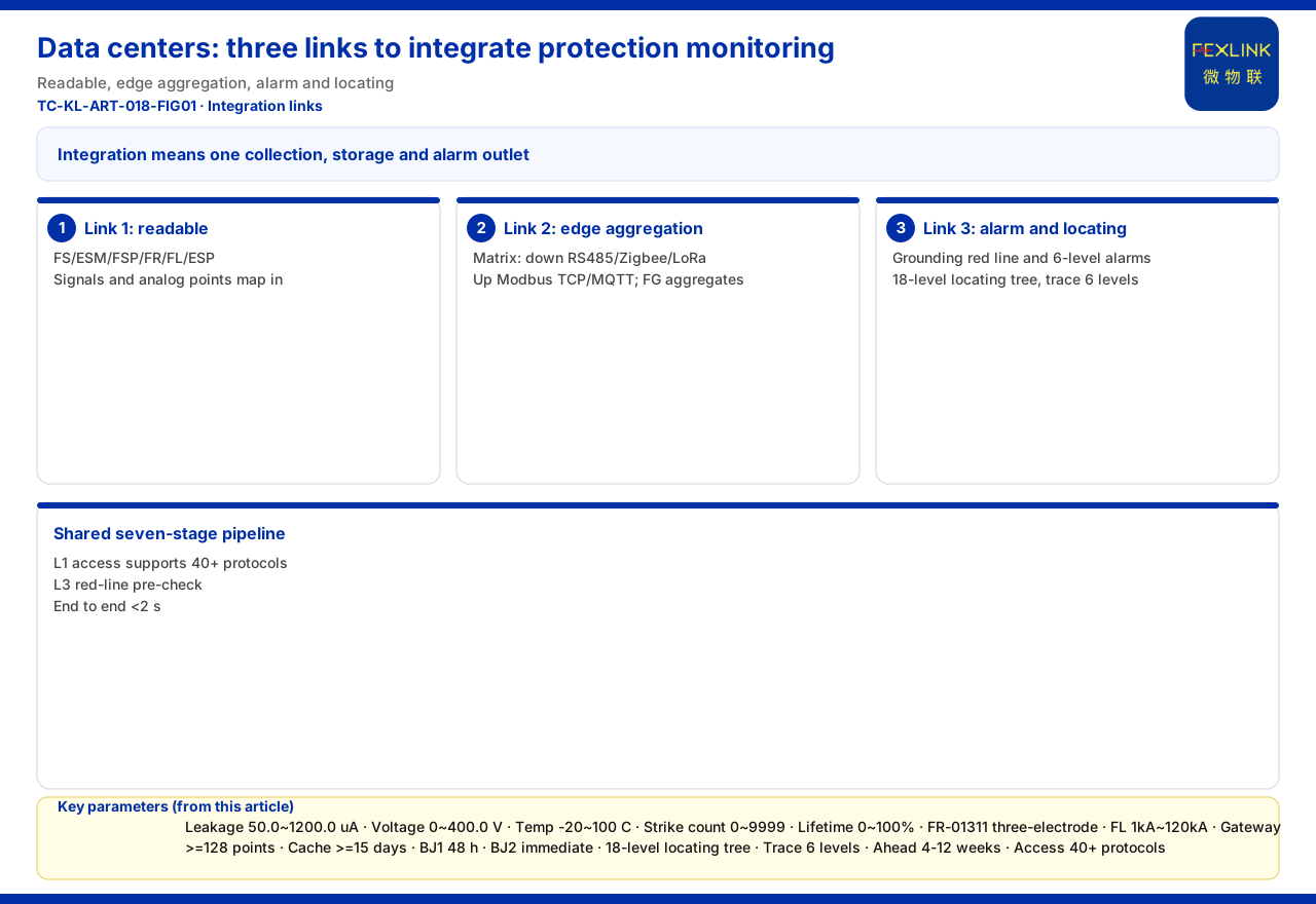
For a data center, "integrating" lightning protection into infrastructure monitoring is rarely about whether monitoring products exist; it hinges on whether three links can be joined: can the protection side's quantities be read out, can they merge into the existing path at the edge, and can events attach to the existing alarm and localisation systems. The knowledge base provides verifiable product and architecture facts: FS/ESM/FSP/FR/FL/FG monitoring capabilities, ESP zero-earth voltage, the four-layer architecture and protocol matrix, and alarms and assessment. But "integrating lightning protection into infrastructure monitoring" is not given as a factual statement in the knowledge base. This article follows the three links.
Why "Integration" Is Not "Installing Another System"
Build lightning protection as a standalone system and operations face one more address, account and inspection round — not stronger judgement. True integration makes protection data and events part of what infrastructure monitoring already contains: the same collection, transmission, storage and alarm outlet as power-distribution and environmental quantities. It is work about interfaces and links, not device count.
The knowledge base defines the monitoring system as four layers — perception, edge, platform, application: the perception layer collects FS/FR/FL/ES modules, smart meters and sensors; edge gateways upload to FEXCloud's platform layer; the application layer presents visualisation, alarms, reports and inspections. These layers are the landing points of integration: if protection data follows the same layering, no separate system is needed.
Link One: Read Out the Protection Side's Quantities
Integration first depends on which readable quantities the protection side offers. The knowledge base lists the FS surge protective device monitor as covering remote signalling, air-switch status, grounding status, lightning-strike count, leakage current, temperature, voltage and lifetime estimation; key parameters include leakage 50.0~1200.0 μA, voltage 0~400.0 V, temperature -20~100 °C, strike count 0~9999 (minimum trigger 0.1 kA) and lifetime 0~100%. These answer the two questions infrastructure monitoring cares about most: is the SPD still in place, and has an event occurred.
Form factors differ. The ESM intelligent monitoring terminal is a full-element terminal adding humidity, with DC5V or AC220V supply; the FSP SPD base provides one remote-signalling input and one strike-count channel, with temperature selectable by model. Grounding is measured by FR-01311 using the three-electrode method, DC12V, outdoor installation, with RS485/Zigbee/Ethernet; strike intensity comes from FL, where FL-01222/FL-01212 cover 1 kA~120 kA with energy monitoring and FL-11122 covers 0.1 kA~1 kA. Indispensable for a data center is the ESP-12101-R zero-earth voltage monitor: neutral-line voltage input, two digital inputs, one relay output and RS485.
The precondition is readable quantities; which model a quantity comes from, and whether it is signalling or continuous, decides whether it lands on a telemetry or telesignal point.
Link Two: Converge the Protocols at the Edge
Once quantities are readable, the second link is to send them into the existing path. The protocol matrix gives the options: device downlinks include Modbus RTU (RS485), Zigbee (Modbus) and LoRa; uplinks include Modbus TCP / MQTT (Ethernet, 4G), with IEC 61850 optional at gateway level. Protection modules can be aggregated through the FG intelligent gateway — a protocol converter with RS485/Zigbee downlink, Ethernet uplink and DC12V supply.
If a system-level grounding gateway is already used, the integration capabilities serve as a capacity reference: ≥128 points with cascading, RS485 ≥4 ports, Ethernet ≥2 ports, optional 4G/5G/LoRa, cache ≥15 days, DC9-36V supply and IP65. These help assess whether many protection points crowd the existing path and whether data is lost when a link breaks, but the knowledge base does not prescribe how to network or plan points.
Link Three: Attach Events to Existing Alarms and Localisation
The highest value is not seeing numbers but that, when a strike happens, a protection event is graded, located and handled like any other infrastructure alarm. The knowledge base makes "abnormal open circuit of the grounding resistance" a non-bypassable red line per GB 50057, and gives a six-level alarm system: BJ1 requires action within 48 hours, BJ2 immediate shutdown, each alarm carrying a standard-clause citation and confidence. A protection safety event can thus inherit existing grading and deadlines instead of remaining a nameless record.
On localisation, the Wanxiang engine maintains independent thresholds and risk models for five electrical-topology position types and an 18-level scenario tree (campus → … → L17 terminal level → L18 contact-point level); its TopologyImpactCalculator traces up to 6 levels of cascading impact. This decides whether the affected distribution segment and terminal can be pinned down rather than reported vaguely.
On trends, the Tianyan engine S-02 residual-current trend-drift (CUSUM) model detects a weak mean shift while leakage is still safe and warns 4-12 weeks ahead, letting a continuous quantity like leakage share a timeline with existing leakage/insulation trends.
Sharing One Time Series and Handling Path
The three links converge on one handling path: the knowledge base describes the Taiyi intelligent-control hub's seven-stage pipeline — L1 ingest → L2 cleansing → L3 red-line pre-check → L4 Qianzhi analysis → L5 Wanxiang assessment → L6 fusion decision → L7 persistence — in under 2 seconds end to end; L1 supports 40+ protocols and an L3 red-line trigger outputs the highest-level alarm and skips weighted computation. Its ingest layer corresponds to the protocol matrix, so integration can reuse existing ingest and alarm outlets.
The pipeline and protocol matrix are the knowledge base's product/architecture facts.
Integration Landing Points for Data Center Scenarios
The knowledge base gives two directly applicable combinations: "data center zero-earth voltage / power-distribution monitoring" recommends ESP-12101 + ESA full-element smart meter + ESX edge gateway; "lightning-arrester condition monitoring (retrofit of existing SPDs)" recommends FS / ESM full-element SPD monitoring / FSP base. The former covers existing power-distribution and zero-earth voltage concerns, the latter adds SPD status and strike events; for the grounding grid, the knowledge base gives "online monitoring of substation/traction-substation grounding grids" with FR-01311 (one set per point) + FG gateway + FEXCloud.
Under the three-link framework, the path is: ESP/ESA for existing distribution monitoring, FS/ESM/FSP to complete protection signal sources, FG or ESX to converge at the edge, then merge with other infrastructure data in FEXCloud and the alarm/localisation systems.
Boundaries: What This Article Does Not Claim
It is not an interface specification, point-table mapping or construction plan.
Second, the quantitative indicators in the knowledge base (electrical-hazard identification 95%+, alarm compression 80%, warning lead 4-12 weeks, fault-localisation time from days to 2 hours, MTTR reduced 60%) are vendor self-reports; cite them only as capability claims, never as integration effects, retrofit effort or procurement grounds.
Third, this article gives no implementation details for DCIM/BMS interface specifications, point-table mapping, sampling and reporting frequency, or offline caching and backfill, and claims no equipotential products or parameters, certification, customer case or integration effect; it invents no model, parameter or standard clause absent from the knowledge base.
Fourth, it does not reuse landing points of registered articles: combining distribution cabinets and weak-current rooms for digital protection, customer data filtering and role layering, lightning's knock-on effects on system safety and alarm grading and tickets.
Conclusion
Integrating lightning protection into a data center's infrastructure monitoring means joining three links: confirm readable quantities on the protection side; converge protocols at the edge; attach events to existing alarm and localisation systems, sharing the seven-stage pipeline. Start from the combinations: ESP+ESA+ESX for distribution and zero-earth voltage, FS/ESM/FSP for protection status and strike events. The value is not more sensors but having protection, power and environmental quantities in one operations view and one alarm outlet.


