
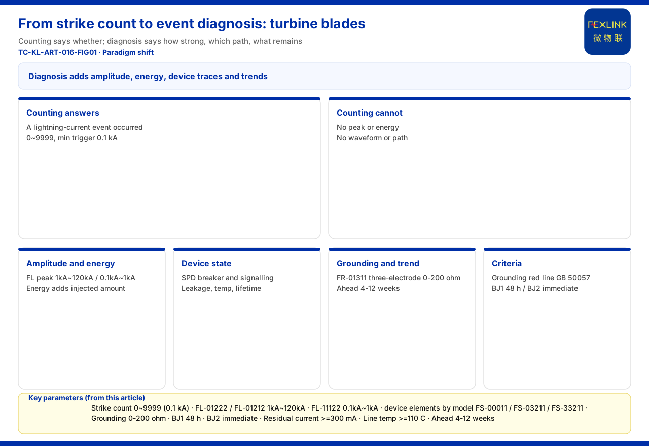
In wind-turbine lightning-protection monitoring, the strike count is easiest to treat as "good enough": a number on screen increments once per hit. But it can only answer "roughly how many hits happened here"; it cannot answer what drives decisions — how strong was this one? Did the blade attachment conduct through the structure, or did the intrusion take another path? What effect did it leave on devices, grounding and operation? Answering them requires moving from "counting" to "event diagnosis".
What the counter answers, and what it misses
The strike count has value. The knowledge base records the FS surge protective device monitor's strike-count range as 0~9999, with a minimum trigger of 0.1 kA. A "minimum trigger" means small-current events may be recorded too, so a count that grows from zero does indicate a lightning-current event occurred here, without waiting for device damage.
But as an event record it has only one integer dimension: no peak, so it cannot separate a small disturbance near the trigger floor from a high-amplitude impulse; no energy, so it cannot judge sustained injected stress; and no waveform or path information. Counting answers "whether"; how hard, along which path, and what was left behind — it cannot answer.
Why the blade magnifies the gap
The knowledge base makes no dedicated proposition about blades. After lightning strikes a blade, the current discharges along structural or conductive paths and may couple into nacelle equipment, electrical circuits and the SPD protection chain. The distinction operators care about: was this attachment on the blade body, or did it enter the system via conduction and induction? Is the intensity enough to stress some link? On a count alone the cases look identical — yet what to inspect and whether to shut down differ. That is why the blade scenario magnifies the "counting is not enough" gap.
Event diagnosis must add "a portrait of one event"
Event diagnosis does not discard counting; it adds, beyond the count, the dimensions needed to reconstruct a single event.
First, amplitude and energy. The FL lightning-current/transient-current monitor provides explicit ranges: FL-01222 (indoor) and FL-01212 (outdoor) span 1 kA~120 kA and support energy (charge/unit energy) monitoring, while FL-11122 (indoor) spans 0.1 kA~1 kA. Peak answers "how strong was this strike"; energy adds "how much was injected over time". The section's model rule also lists function tiers — 1=peak, 2=peak+energy, 3=waveform, 4=waveform+energy — showing that moving from "recording a number" to "recording an event portrait" is available in tiers within the existing product system.
Second, the protection device's own state and post-event traces. FS monitoring covers remote signalling, air-switch status, grounding, strike count, leakage, temperature, voltage and lifetime estimation; FS-00011 has only signalling, air switch, grounding and strike count, while FS-03211 and FS-33211 progressively add leakage, temperature, voltage and lifetime estimation. The ESM full-element terminal also includes humidity, with DC5V or AC220V supply; the FSP likewise provides one remote-signalling input and one strike-count channel. Air-switch status and signalling show whether the SPD is connected, tripped or alarming — direct evidence for whether the protection chain is intact.
Third, linking the event to grounding and degradation trends. The FR-01311 uses the three-electrode method, DC12V supply and outdoor installation, with RS485/Zigbee/Ethernet; it gives system-level reference parameters, such as a monitoring unit of 0-200 Ω (standard, ±1%), an intelligent gateway mounting ≥128 points and ≥15 days of data caching. If leakage or temperature rises after an event, adding the actual grounding-resistance reading creates a chance to separate "device under stress" from "grounding-grid anomaly", rather than labelling a single value outright.
From data to criteria: red lines, grading and trends
Once the event portrait is captured, criteria are still needed to turn data into action. The knowledge base lists "abnormal open circuit of the grounding resistance" as the non-bypassable red line, per GB 50057; a trigger emits the highest-level alarm and skips weighted computation. In the same section's six-level alarm scheme, BJ1 (20-39) requires action within 48 hours and BJ2 (0-19) requires immediate shutdown, each alarm carrying a standard-clause citation and confidence. Safety-baseline signals must therefore be handled before equipment-health signals.
The same section also lists five red lines and a seven-dimensional perception matrix, where residual current ≥300 mA (per GB 13955) and line temperature ≥110 °C (per GB 16895), with D7 a 0-100 time-series risk score. On trends, the Tianyan engine S-02 residual-current trend drift (CUSUM) model detects a weak mean shift while leakage is still safe, warning 4-12 weeks ahead. The amplitude, energy and SPD state at the moment of the event answer "what happened"; the red lines and trend model answer "should we act now, and which changes deserve continuous tracking".
Data trust: four-layer architecture and protocol paths
Event diagnosis also assumes the data really did arrive completely. The knowledge base defines the monitoring system as four layers — perception, edge, platform, application; the protocol matrix gives device downlinks (Modbus RTU/RS485, Zigbee, LoRa) and uplinks (Modbus TCP/MQTT; IEC 61850 optional at gateway level); lightning-protection module data is aggregated through the FG intelligent gateway, a protocol converter with RS485/Zigbee downlink, Ethernet uplink and DC12V supply. Lightning can affect power and communications at once, so a missing value is sometimes a fault and sometimes a link problem — confirm the path first.
What this shift changes in O&M decisions
Counting-to-diagnosis is not "a few more numbers" but a different decision layer. With counting alone, operators arrange by experience for "it was hit"; an event portrait lets them weigh severity by amplitude and energy, judge the protection chain by SPD state, and choose immediate, time-limited or planned action by grounding and leakage trends. On the platform side, the Taiyi intelligent-control hub's seven-stage pipeline (L1 ingest→L2 cleansing→L3 red-line pre-check→L4 Qianzhi analysis→L5 Wanxiang assessment→L6 fusion decision→L7 persistence) runs in under 2 seconds end to end, and an L3 red-line trigger emits the highest-level alarm directly. The quantitative indicators (electrical-hazard identification 95%+, fault-localisation days→2 hours, MTTR −60%, etc.) are vendor self-reports; cite them only as capability claims, not as effect guarantees or procurement grounds.
Boundaries: what this article does not claim
Second, this article provides no blade-specific model or certification, blade damage rate, energy-yield loss or payback data, and claims no diagnosis effect, customer case or project performance; the knowledge base does not cover these, so no assertion is made.
Third, no implementation details are given for sampling and reporting frequency, offline caching and backfill; no standard clause is inferred; only the standard names GB 50057, GB 13955 and GB 16895 listed in the knowledge base are cited.
Fourth, this article carries only the paradigm-shift landing point for the specific object of the wind-turbine blade, without repeating the above or reusing old drafts.
Conclusion
Strike counting is not wrong; it can only answer "was it hit". A blade's high-exposure position makes "how strong was this one, along which path, and what did it leave behind" a question operators need answered — exactly the dimensions event diagnosis adds: characterise the event with FL peak and energy, judge device stress with FS/ESM/FSP SPD state, leakage, temperature and lifetime estimation, confirm site and data trust with FR and grounding parameters plus protocol paths, then form handling criteria from the red lines and six-level alarms and the trend model. Counting-to-diagnosis upgrades "this place was hit" into "what happened, and what to do".


