
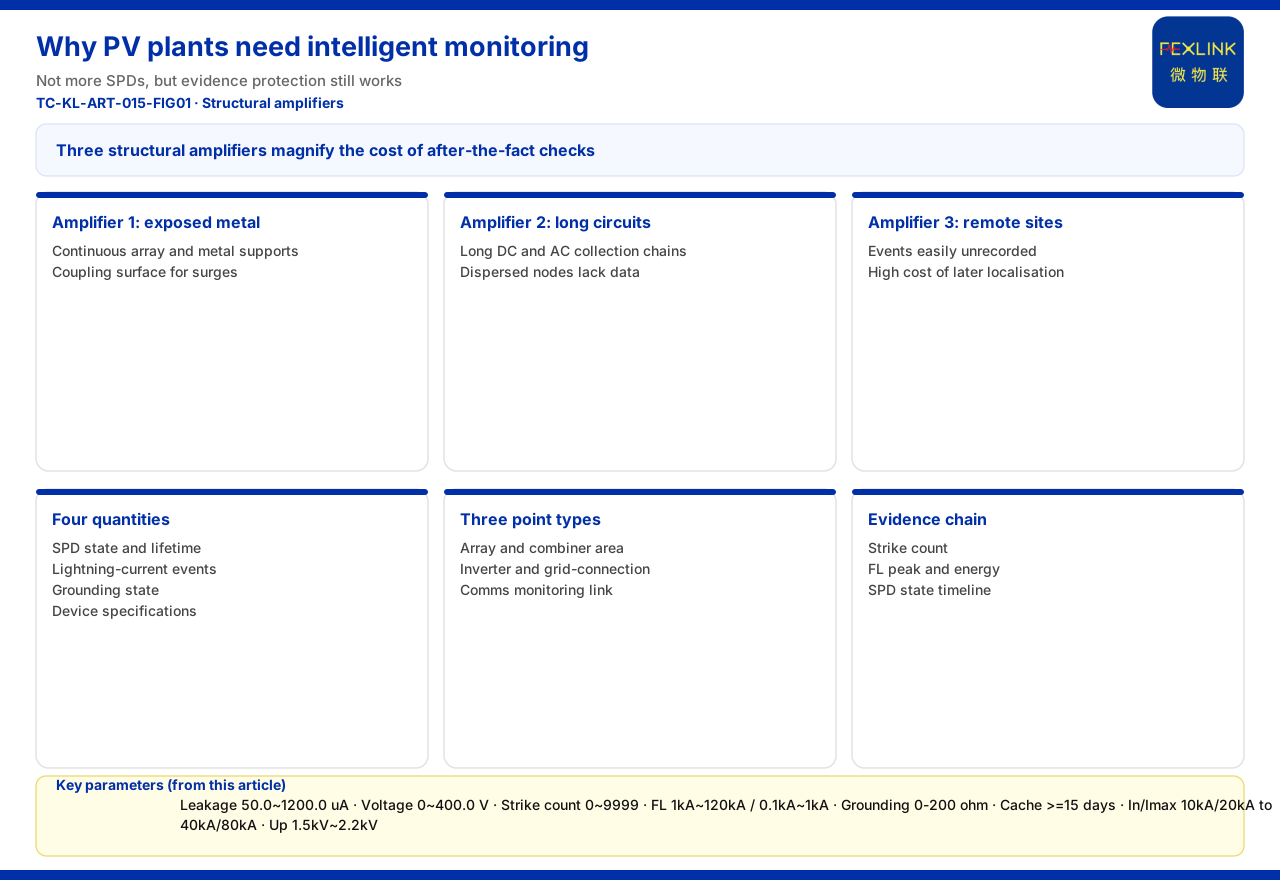
What a PV plant usually needs is not "one more SPD" but "to know whether its protection still works". Large exposed metal surfaces on arrays and supports, long dispersed DC and AC circuits, and remote, lightly staffed sites make lightning and surge events easy to leave unrecorded. Intelligent monitoring turns SPD status, lightning-current events and grounding status into continuously visible data.
Conclusion First: What a PV Plant Lacks Is Not SPDs but Evidence That Protection Still Works
Lightning-protection engineering requires everything specified to be installed — surge protective devices on the power side, signal arresters on the signal side, a compliant grounding grid. But "installed" only means the design met the standard, not that it still works after a strike. SPDs are consumables that may degrade after lightning or sustained overvoltage; grounding grids drift with soil, construction and season; and lightning is a low-frequency event manual watchkeeping rarely catches. Intelligent monitoring answers precisely these post-installation questions: the SPD's present state, whether it has been struck, and whether grounding is still reliable.
Three Structural Amplifiers: Why PV Risk Is Not Evenly Distributed
They explain why the same protection configuration needs monitoring more in a PV setting.
Amplifier One: Large Exposed Metal Surfaces
A PV plant is dominated by component arrays and metal supports with a large, continuous footprint. The array is both an asset and a possible surge-coupling surface: direct strikes and induced overvoltage can both travel along supports, module frames and combining paths. Traditional protection asks "is there an air terminal, is there grounding" but rarely "what did this metal body endure in a thunderstorm".
Amplifier Two: Long, Dispersed DC and AC Circuits
From strings to combiner boxes to inverters is a dispersed, fairly long DC chain; from inverters to box transformers and grid cabinets is another AC collection chain. The longer the circuit and the more dispersed the nodes, the more opportunities for surge coupling, yet "which section fails first" often lacks data, and manual inspection cannot cover every point or storm window.
Amplifier Three: Remote, Lightly Staffed Sites Amplify After-the-Fact Cost
An undetected surge may only draw attention when equipment misbehaves and generation suffers — by then it is hard to reconstruct whether lightning, SPD ageing or grounding failed first. The greater the operating distance, the higher the cost of after-the-fact localisation.
Blind Spots of Traditional Practice: Degradation and Breakdown Are Often Invisible
Traditional practice has two blind spots. SPD degradation is gradual; its appearance need not be abnormal and an inspection may not measure it, so protection can be "nominal only" by the time it fails in the next surge. Periodic testing reflects only the instant of testing, while lightning is random, so impacts between tests go unrecorded. The asymmetry: heavy investment in protection, no continuous evidence that it still works. Intelligent monitoring fills that gap.
What a PV Plant Should Monitor: Four Quantities, Three Locations
The knowledge base gives clear entries for what can be monitored; quantities and parameters are the knowledge base facts.
- **SPD state and lifetime**: the FS surge protective device monitor covers remote signalling, air-switch status, grounding status, lightning-strike count, leakage current, temperature, voltage and lifetime estimation, with key parameters leakage current 50.0~1200.0 μA (±10 μA), voltage 0~400.0 V (±0.1 V), temperature -20~100 °C (±1 °C) and lifetime estimation 0~100%; the ESM intelligent monitoring terminal includes humidity among its full elements and supports DC5V or AC220V. - **Lightning-current events**: FL-01222 (indoor) and FL-01212 (outdoor) cover a 1 kA~120 kA peak range with energy monitoring; FL-11122 (indoor) covers 0.1 kA~1 kA; the FS strike count is 0~9999 with a 0.1 kA minimum trigger. - **Grounding status**: the FR-01311 grounding resistance monitor uses the three-electrode method, DC12V and outdoor installation with RS485/Zigbee/Ethernet; system-level reference ranges include 0-200 Ω (standard type, ±1%), and the gateway data cache is ≥15 days. - **Protective-device specifications**: the knowledge base also lists the FSS intelligent surge protective device (In/Imax 10 kA/20 kA to 40 kA/80 kA, Up 1.5 kV~2.2 kV, AC220V), and YSE-series power/signal arresters (including DC48/24/12V and signal arresters), as supporting components.
The three locations are the array/combining area, the inverter and grid-cabinet area, and the communication link — concerning lightning intrusion and grounding paths, power and SPD status, and signal-side surges. Selection must be confirmed on site.
From "Event" to "Evidence": Why PV Plants Need an Evidence Chain
For a PV plant, monitoring also carries an easily underestimated value: evidence. Lightning is low-frequency and high-consequence, and a site often must answer "was it struck, how hard, was protection normal then". The strike count, FL peak and energy monitoring, and the SPD state-change timeline form a traceable evidence chain, persuasive for liability, insurance and later upgrades. It also enables "zoned records" — judging which area is struck more often and which device type degrades faster, turning "patrol the whole site" into "treat high-risk areas first".
How the Platform Turns Monitoring into Action
Once data is in the cloud, the question is whether it becomes action. The knowledge base gives a four-layer architecture: perception-layer FS/FR/FL/ES modules pass through an edge gateway (FG/ESX/CW) to the FEXCloud platform layer, rendered by the application layer as visualisation, alarms, reports and inspections. The protocol matrix supports RS485/Zigbee/LoRa downlinks and Modbus TCP/MQTT plus optional gateway-level IEC 61850 uplinks; the FG gateway is a protocol-conversion type with RS485/Zigbee downlink, Ethernet uplink and DC12V. On the platform side, the Taiyi hub runs a seven-stage pipeline end to end in under 2 seconds, applicable to renewable-energy plants. Two mechanisms matter most: abnormal open circuit of the grounding resistance is the non-bypassable red line (per GB 50057), triggering the highest alarm directly, and in the six-level scheme BJ1 (20-39) requires action within 48 hours while BJ2 (0-19) requires immediate shutdown; and the Tianyan engine's S-02 residual-current trend drift (CUSUM) model detects a weak mean shift while leakage is still safe, warning 4-12 weeks ahead. The harmonic fingerprint library also includes an FP-12 PV-inverter fingerprint.
Boundaries: What This Article Does Not Claim
The knowledge base recommends "arrester condition monitoring (retrofit of existing SPDs)" (FS/ESM/FSP) and "online monitoring of substation and traction substation grounding grids" (FR-01311 + FG + FEXCloud), with no PV-specific row. Site-specific selection and monitoring locations must therefore be confirmed item by item against the site's design, grounding conditions and operational requirements.
Second, the knowledge base indicators (electrical-hazard identification 95%+, alarm compression 80%, 4-12 weeks' warning, fault localisation from days to 2 hours, MTTR down 60%, energy saving 8-20%) are vendor self-reports — citable only as vendor capability claims, never as generation revenue, payback or procurement grounds.
Third, this article provides no PV-specific SPD parameters, string-level measuring-point design specification, generation-loss model or payback calculation, and claims no case, certification or performance data; it invents no model, parameter or standard clause absent from the knowledge base.
Fourth, it reuses no landing points of registered articles: not the existing-SPD upgrade path, engineering-firm organisation and service transformation, the general argument that lightning interrupts system operation, contracting and business models, or the shift from annual testing to continuous risk service.
Conclusion
A PV plant needs intelligent lightning-protection monitoring not because it has too few SPDs, but because its engineering structure conceals "protection failure": large exposed metal, long dispersed combining and collection circuits, and remote, lightly staffed operation amplify the cost of after-the-fact investigation. Use verifiable quantities to close that visibility gap — FS/ESM for SPD state and lifetime, FL for lightning-current events, FR for grounding status — aggregated via FG and FEXCloud, with the platform guarding red lines and warning on trends. The method can be borrowed, but the plan and its effects still require item-by-item verification against project and compliance requirements.


