
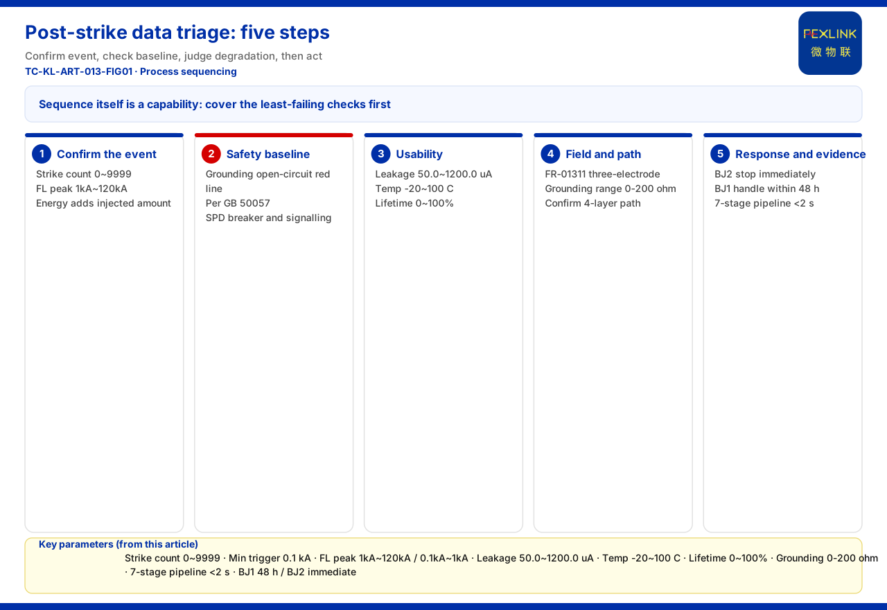
After a thunderstorm, operators ask two things: did the strike hit us, and is anything wrong now? The answer is rarely "check every channel" but a matter of sequence. This article gives a post-strike data triage path ordered by time sensitivity: confirm the event and its size, confirm the safety baseline, judge whether the equipment can keep serving, then localise, handle and preserve evidence.
Why "First" Is a Sequencing Problem
A strike leaves traces on several channels within seconds while raising noise; checking item by item burns the most valuable minutes on irrelevant fluctuation. Three "whethers" come first — did a strike occur, is there an immediate safety problem, is availability already affected — and they are not equally urgent. The five steps follow that urgency.
Step One: Confirm Whether and How Hard
The most direct "were we hit" quantity is the lightning-strike count: the knowledge base records 0~9999 strikes for the FS surge protective device monitor, minimum trigger 0.1 kA. Small-current events are recorded too, so a changed count indicates a real lightning-current event without waiting for damage. "How hard" comes from FL monitoring: the knowledge base gives FL-01222 (indoor) and FL-01212 (outdoor) 1 kA~120 kA with energy monitoring, and FL-11122 (indoor) 0.1 kA~1 kA. Peak answers how strong the strike was; energy adds how much was injected.
Do this first because if count and peak did not move, later steps are likely chasing unrelated fluctuation; if an event did occur, later abnormal values deserve to be read as its consequences.
Step Two: Check the Safety Baseline Immediately
Once an event is confirmed, the priority is not "is the equipment broken" but "is it safe now". The knowledge base makes "abnormal open circuit of the grounding resistance" the non-bypassable red line, per GB 50057; a trigger emits the highest-level alarm. The first glance belongs to baseline signals such as grounding status: if they are abnormal, equipment lifetime and maintenance plans are moot.
Protection-device state matters too. FS monitoring covers remote signalling, air-switch status, grounding status, strike count, leakage current, temperature, voltage and lifetime estimation; the FSP SPD base provides remote-signalling input and strike-count monitoring. Air-switch status and signalling show whether the SPD is still connected, tripped or alarming, deciding whether the protection chain is intact.
Leakage current is the most easily misread quantity and worth a look now. The knowledge base gives FS leakage 50.0~1200.0 μA (±10 μA), temperature -20~100 °C (±1 °C) and voltage 0~400.0 V (±0.1 V). A clear rise usually means the device took stress, but one value cannot settle it, so the step-three trend is needed. In the six-level scheme, BJ2 (0-19) requires immediate shutdown and BJ1 (20-39) action within 48 hours, showing safety signals outrank equipment-health signals.
Step Three: Judge Whether It Can Still Be Used
Only then comes whether the equipment can keep running and whether to replace it soon. FS leakage, temperature and lifetime estimation (0~100%) give continuous device-side observations; the ESM intelligent monitoring terminal adds humidity and offers DC5V or AC220V.
On trends, the knowledge base records the Tianyan engine's S-02 residual-current trend drift (CUSUM) model, detecting a weak mean shift while leakage is still safe and warning 4-12 weeks ahead. Whether the post-strike leakage curve shifts persistently separates a lasting effect from a momentary disturbance. This step may be handled later but must be scheduled early: equipment may not fail at once yet may have entered accelerated degradation, turning "repair after failure" into "replace before expiry".
Step Four: Return to the Site and the Path
The first three steps run on the platform, but judgement must land on site and answer a precondition: is the data trustworthy, and was it interrupted? The key cross-check is grounding. The knowledge base describes the FR-01311 grounding resistance monitor using the three-electrode method, DC12V supply and outdoor installation, with RS485/Zigbee/Ethernet; it gives system-level reference ranges (e.g. 0-200 Ω standard type). If grounding status or leakage is abnormal, the actual resistance reading helps tell device from grounding grid.
At path level, check data completeness. The knowledge base gives device downlinks (Modbus RTU/RS485, Zigbee, LoRa) and uplinks (Modbus TCP/MQTT; IEC 61850 optional at gateway level); lightning-protection module data is aggregated by the FG intelligent gateway, a protocol converter with RS485/Zigbee downlink, Ethernet uplink and DC12V supply. A strike can affect power and communications, so a missing value is sometimes a fault and sometimes a link problem; the four layers — perception, edge, platform, application — frame this check.
Step Five: Escalate, Handle and Preserve Evidence
When the baseline is crossed or degradation confirmed, response begins. The first basis is alarm level and deadline: in the six levels, BJ2 requires immediate shutdown and BJ1 action within 48 hours, each alarm carrying a standard-clause citation and confidence. Handling advice should follow these known boundaries, not add measures by rule of thumb.
Platform support is the Taiyi intelligent-control hub's seven-stage pipeline — L1 ingest → L2 cleansing → L3 red-line pre-check → L4 Qianzhi analysis → L5 Wanxiang assessment → L6 fusion decision → L7 persistence — in under 2 seconds end to end; an L3 red-line trigger emits the highest-level alarm, so safety anomalies surface fast. Evidence also documents the event: a timeline of strike count, peak, energy and actions taken supports review and liability definition (the knowledge base sets no evidence format or retention period).
How to Use This Path on Site
Configurations differ. In the knowledge base, "lightning-arrester condition monitoring (retrofit of existing SPDs)" recommends FS, ESM full-element SPD monitoring and the FSP base, focused on strike count, SPD status and leakage; "online monitoring of substation and traction-substation grounding grids" recommends FR-01311 (one per point) plus an FG gateway plus FEXCloud, focused on grounding status and resistance.
Boundaries: What This Article Does Not Claim
It is not a standard operating procedure and cannot replace site rules or safety regulations.
Second, the quantitative indicators in the knowledge base (electrical-hazard identification 95%+, alarm compression 80%, 4-12 weeks' warning lead, MTTR reduced 60%) are vendor self-reports. Cite them only as vendor capability claims, never as handling deadlines, guarantees or procurement grounds.
Third, no implementation details are given for sampling and reporting frequency, offline caching and backfill, or alarm-ticket grading; no customer case, certification or handling effect is claimed; no model, parameter or standard clause absent from the knowledge base is invented.
Fourth, landing points of registered articles are not reused: customer data filtering and role layering, low-bid cost consequences, installed-versus-effective criteria, lightning's knock-on effects on system safety and alarm-grading tickets. It answers only the order in which to check data first after a strike.
Conclusion
The hard part is not how much to look at but what to look at first. The path: confirm the event with strike count and FL peak and energy; confirm safety with the grounding red line, SPD status and leakage; judge degradation with leakage trend, temperature and lifetime; confirm site and data trust with grounding measurement and protocol paths; then handle and document via alarm levels and the seven-stage pipeline. The order itself is a capability: it lets limited manpower cover the most error-intolerant judgements first.


