First Read "Cascadable" Accurately
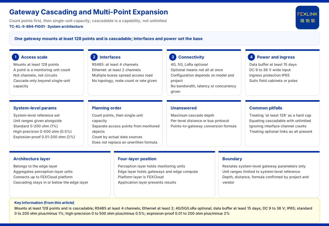
The question "how to plan gateway cascading and multi-point expansion" is easy to answer wrong at the first step: treating "cascadable" as a capability that can be stacked at will, without distinguishing what the documentation does and does not say. The reference parameters the product documentation gives for the system-level intelligent gateway are: no fewer than 128 mounted points, and cascade-capable; on interfaces, no fewer than 4 RS485 ports and no fewer than 2 Ethernet ports; communication methods 4G, 5G, and LoRa optional; a data cache of no less than 15 days; a DC 9 to 36 volt wide-voltage supply; and an IP65 protection rating. This parameter set describes the access scale and interface margin of a single gateway but says nothing about the maximum cascade depth, single-stage distance, or bus protocol. Planning can therefore read "cascadable" only as the existence of a capability and cannot infer a specific depth or wiring plan from it.
The Access Scale of a Single Gateway
The documentation says no fewer than 128 mounted points. Here a "point" means the number of connected monitoring units, not the number of channels or circuits. Taking it as the planning starting point means that under the documented definition a single gateway is sufficient to carry a medium-scale set of multi-point monitoring units; only when the point count rises beyond the capacity of one gateway does cascading become necessary for expansion. The documentation gives no conversion formula for "how many points require cascading" and no correspondence between expansion points and the number of gateways, so it cannot simply be written as "one more gateway per 128 points."
The Interface Makeup Determines the Expansion Method
The interfaces of the system-level intelligent gateway are no fewer than 4 RS485 ports and no fewer than 2 Ethernet ports. RS485 usually corresponds to field-bus serial access, and multiple ports mean several bus branches can be connected at once; Ethernet ports correspond to higher-bandwidth access or cascade links. The documentation gives only the lower bounds of interface counts and does not state the wiring topology, maximum node count, or rate of each port, so how these interfaces are combined must be determined by the project against field conditions. What can be confirmed is that the interface count itself is the material basis of expansion: when one bus approaches its capacity, access pressure can be spread by adding bus branches instead of crowding everything onto one link.
The Meaning of Optional Communication Methods
The documentation lists 4G, 5G, and LoRa as optional communication methods. Optional means these methods are not all present at once, and the specific configuration depends on the model and project choice. They address scenario differences: use wired where it is reachable, consider cellular where wiring is difficult or long-distance backhaul is needed, and use LoRa aggregation where the measuring points are themselves wireless devices such as temperature probes. The documentation gives no bandwidth, latency, or concurrency capability for each method, so it cannot describe how many points a method suits.
Environmental and Supply Parameters
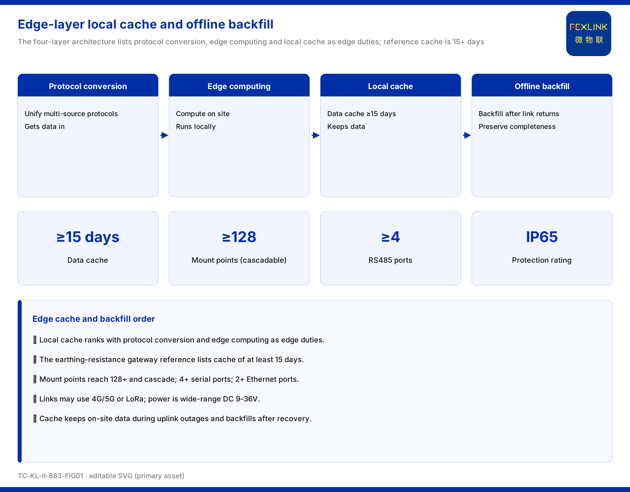
A data cache of no less than 15 days means the gateway can retain field data for a period when the uplink is interrupted, easing backfill after recovery. A DC 9 to 36 volt wide-voltage supply means it can work over a wide range of supply variation. An IP65 protection rating means it has some protection against dust and water spray and suits a field cabinet or pole outside the distribution box. These three are installation and operating conditions; they do not change the access scale itself but are constraints that must be considered together when planning the gateway's installation position.
Why This Parameter Set Is Filed Under "System Level"
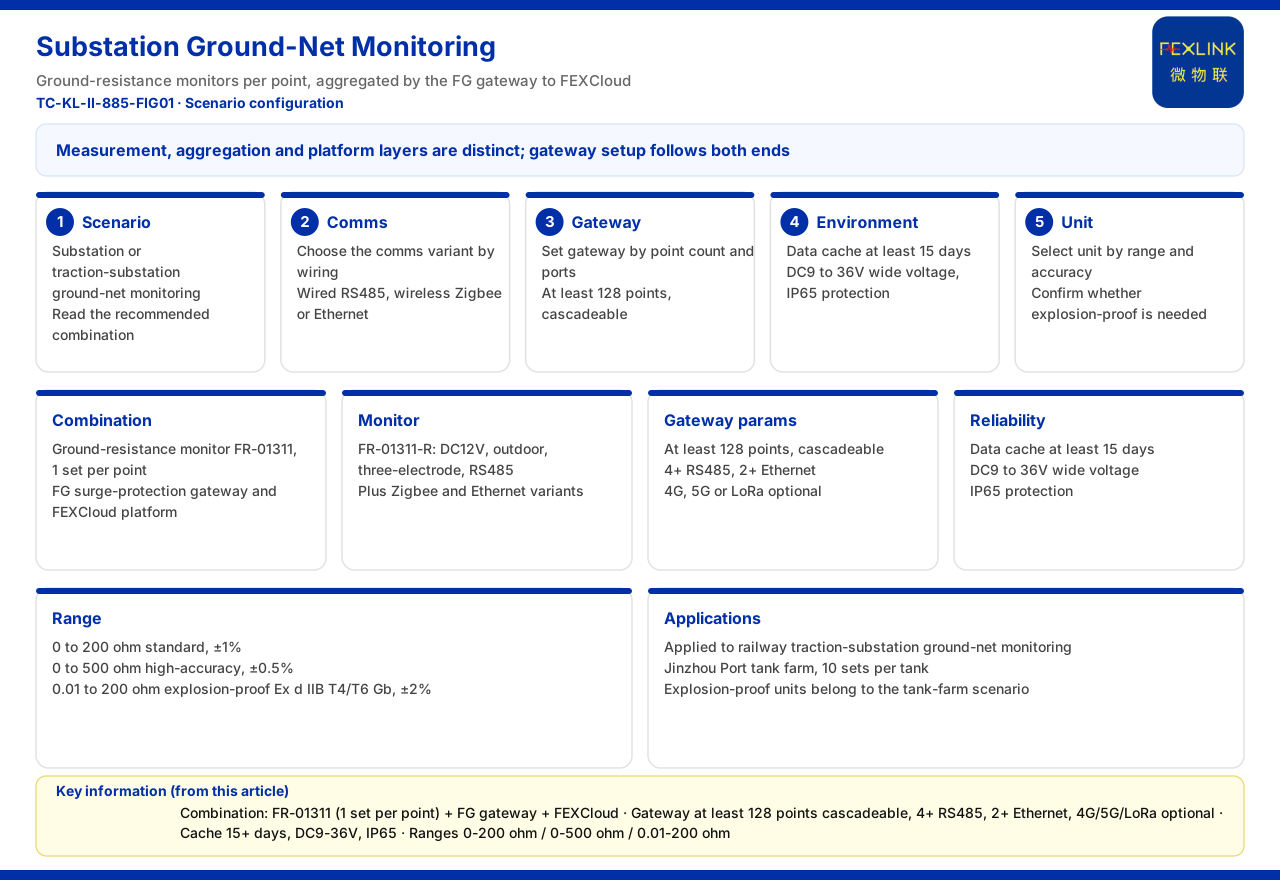
The documentation files these gateway parameters under "grounding resistance monitoring system (system-level) reference parameters" and at the same time gives the monitoring unit ranges: standard type 0 to 200 ohms at ±1% accuracy; high-precision type 0 to 500 ohms at ±0.5% accuracy; and explosion-proof type 0.01 to 200 ohms at ±2% accuracy. This shows that "system level" is a complete reference configuration formed by monitoring units, gateways, and the platform together, in which the gateway carries the aggregation and upload role rather than being an isolated device. Discussing the gateway and the monitoring units separately in planning easily overlooks that they are defined as a set.
The Gateway's Position in the General Architecture
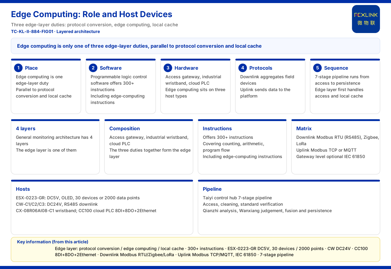
The documentation gives a general four-layer architecture for the monitoring system: perception layer, edge layer (containing the lightning-protection smart gateway, intelligent edge-computing gateway, industrial gateway, and cloud PLC), platform layer (FEXCloud), and application layer. The system-level intelligent gateway belongs to the edge layer, docking upward with the platform and aggregating the various monitoring units of the perception layer downward. Understanding this layer position helps judge where cascading occurs: it occurs inside the edge layer or between the edge layer and the perception layer, not by building a separate link past the platform layer. The documentation gives no specific networking rules inside the edge layer, and this article does not supplement them.
Two Reminders on the Planning Order
First, count the points before looking at the capacity of one gateway. The number of monitoring units to be connected on site is the starting point of planning; comparing it with the "no fewer than 128 points" definition of a single gateway gives a preliminary judgment of whether expansion is needed. If the point count does not exceed the capacity of one gateway, there is no need to expand for expansion's sake. Second, distinguish "physical access points" from "monitored objects." The same monitored object may correspond to several points, and planning should count by the data sources actually requiring upload rather than roughly converting room or device counts. Neither reminder replaces the conversion formula the documentation omits; they simply use the known parameters in the right place.
Questions the Documentation Does Not Answer
The documentation gives no maximum cascade depth of the intelligent gateway, no single-stage cascade distance or bus protocol, and no conversion formula between expansion points and the number of gateways. These three are exactly the inputs a field wiring plan most needs. Their absence means any statement such as "how many levels at most," "how far each stage," or "how many points per gateway" lacks documentation support. The planning stage should list these as items to confirm, to be supplemented by product material or manufacturer technical support, rather than replacing them with empirical values.
Common Misunderstandings in Planning
The first misunderstanding is to treat "no fewer than 128 mounted points" as an exact upper limit, ignoring that "no fewer than" states a lower bound. The second is to equate "cascadable" with "cascade at will," ignoring that the documentation gives no depth or distance limit. The third is to look only at point count and not at interfaces, ignoring that the RS485 and Ethernet port counts determine the available access branches on site. The fourth is to treat optional communication methods as simultaneously present, ignoring that the specific configuration depends on the model and project. Separating these points is what makes the planning assumptions sound.
Boundary Statement
First, this article restates only the documented parameters of the system-level intelligent gateway, namely no fewer than 128 mounted points and cascade-capable, no fewer than 4 RS485 ports, no fewer than 2 Ethernet ports, 4G and 5G and LoRa optional, a cache of no less than 15 days, DC 9 to 36 volt wide voltage, and IP65 protection, and does not extend to unlisted performance indicators. Second, the monitoring unit ranges are limited to those listed in the system-level reference parameters and do not infer other ranges across systems. Third, the architectural layers are limited to the general four-layer description and do not infer networking rules inside the edge layer. Fourth, the maximum cascade depth, single-stage distance, and point-conversion formula are documentation gaps that must be confirmed by the project and the manufacturer, and this article does not infer them.