Direct answer
The model number of a lightning-protection smart gateway is not a random string of characters but a code that can be read segment by segment: it writes the gateway type, the mounting method, the power supply and the downlink and uplink communication modes into the model in turn. According to the product material, the complete rule is "FG – gateway type, mounting method, power supply – downlink, uplink", where the gateway-type field uses codes to distinguish capability, 01 being transparent transmission and 02 protocol conversion. Understanding this rule lets one read directly from the model whether the device performs simple forwarding or protocol conversion, and which downlink interface it uses toward the field and which uplink interface it uses to return data to the platform. This section gives the conclusion first and then explains the meaning of each field and the difference between two examples.
1. The overall structure of the model rule
The model rule given by the product material is: after FG there are two groups of fields, the first group made up of the gateway type, the mounting method and the power supply together, and the second group made up of the downlink and uplink communication modes together. This writing of "prefix plus two segments" lets the model carry both the device form and the access capability. The first group answers "what gateway is this, how is it mounted, what does it use for power", and the second group answers "what is connected on the field side and how is it transmitted on the platform side". Splitting form and access into two segments makes it easy to combine different models within the same product family according to field conditions, without having to start a new naming set for every combination.
2. The gateway-type field: the difference between 01 and 02
The first digit of the first group is the gateway-type code, and the product material specifies 01 as transparent transmission and 02 as protocol conversion. Transparent transmission means the device mainly plays the role of forwarding data upward; protocol conversion means the device must complete conversion between different protocols before outputting to the platform. Although this digit has only two values, it determines the role of the device on the data link: transparent transmission leans toward a channel, protocol conversion toward adaptation. Therefore, when several downlink protocols exist on site or the platform-side protocol needs to be unified, reading this digit in the model quickly tells whether the model has the corresponding conversion capability.
3. Mounting method and power-supply fields
After the gateway type, the first group has the mounting method and power-supply fields in turn. The product material illustrates the power-supply writing with two examples of the lightning-protection smart gateway: FG-0221-ER and FG-0221-EZ are both powered at DC12V. That is, the power-supply field at the end of the first group fixes the DC twelve-volt condition into the code, making it easy to select according to the supply available on site. That the mounting-method field appears alongside the power-supply field shows that both are regarded as constraints that must be clarified during selection, rather than as additional information to be filled in later.
4. Uplink/downlink fields and common suffixes
The second group of the model is made up of the downlink and uplink fields, whose values depend on the common-suffix convention in the product material: -R is RS485 running Modbus; -E is Ethernet running MQTT; and -Z is Zigbee running Modbus. Connecting this suffix set to the second group lets one read the access difference of the two examples. It should be stressed that the common suffixes are a communication-mode convention shared by the whole series, while the lightning-protection smart gateway model expresses the downlink and the uplink each with one letter, so that "what the field uses and how the platform transmits" is fully recorded within two or three characters. Understanding the suffix convention is the premise for correctly reading the second group of an FG model.
5. The access difference of the two examples
According to the product material, FG-0221-ER has RS485 on the downlink and Ethernet on the uplink; FG-0221-EZ has Zigbee on the downlink and Ethernet on the uplink. Both are protocol-conversion gateways, both powered at DC12V, and the difference is concentrated in the downlink field: the former accesses by RS485, the latter by Zigbee. This comparison shows that the latter part of the FG model distinguishes the access mode by the uplink/downlink combination: when the field is dominated by a wired serial bus, choose the combination with R on the downlink; when the field wishes to reduce cabling and acquire wirelessly, choose the combination with Z on the downlink. The uplink field is the same for both, both returning to the platform over Ethernet, which shows that in this family the choice of uplink interface is relatively independent of the downlink interface.
6. Edge-layer positioning and duties
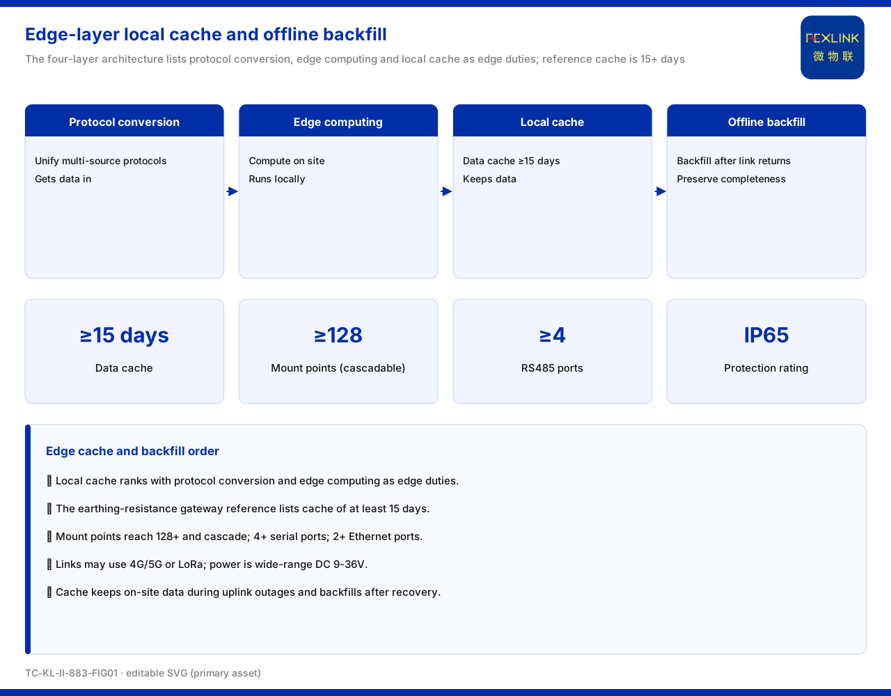
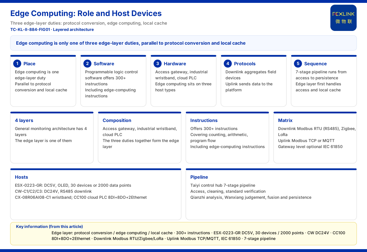
In the general four-layer monitoring-system architecture described by the product material, the lightning-protection smart gateway sits at the edge layer, together with the ESX intelligent edge-computing gateway, the CW industrial gateway, the CX industrial wearable and the CC cloud PLC, carrying the duties of protocol conversion, edge computing and local caching. Reading this positioning together with the model rule, the gateway type and the uplink/downlink fields in the model are exactly the mapping of the edge-layer duties at the naming level: protocol conversion corresponds to the type field, data aggregation to the uplink field, and field adaptation to the downlink field. The existence of the edge layer lets the data of the perception layer be organised and cached once before entering the platform layer, rather than pushing raw data straight to the platform.
7. Correspondence with the protocol matrix
The communication protocol matrix of the product material specifies that device downlink protocols include Modbus RTU (based on RS485), Zigbee (based on Modbus) and LoRa, and device uplink protocols include Modbus TCP and MQTT, carried over Ethernet or 4G. The uplink/downlink fields of the lightning-protection smart gateway correspond to this matrix: downlink with R corresponds to Modbus RTU over RS485, downlink with Z to Modbus over Zigbee, and uplink with E to MQTT over Ethernet. Once the model fields and the protocol matrix are aligned, selection no longer requires memorising isolated letters but can follow the line "field to protocol, protocol to bearer" to check whether the field conditions match the platform requirements.
8. Access and aggregation in a typical scenario
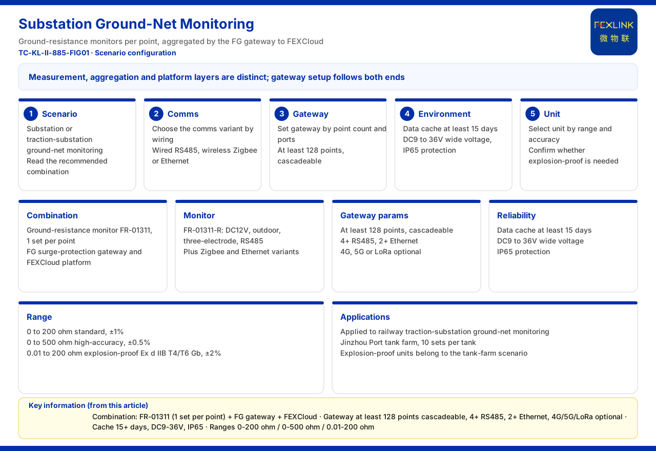
The typical application scenarios and selection comparison of the product material give the combination for online grounding-grid monitoring of substations and traction substations: the grounding resistance monitor configured as one set per point, used together with the lightning-protection smart gateway and the FEXCloud platform. In this combination the grounding resistance monitor acquires the grounding-grid data, the lightning-protection smart gateway handles access and aggregation, and the platform handles subsequent presentation and management. This shows that the positioning of the lightning-protection smart gateway is not limited to the data channel of the surge protector itself but can serve as an edge aggregation node of a lightning-protection-related monitoring system, organising dispersed monitoring points before uploading them uniformly.
Scope and limitations
- This article is limited to the existing statements of the product material on the lightning-protection smart gateway model rule, the common suffixes, the four-layer architecture positioning, the communication protocol matrix and the typical-scenario selection; it makes no inference about unlisted specific parameters or deployment conclusions. - The gateway-type codes in the model fields (01 transparent transmission, 02 protocol conversion), the power-supply condition (DC12V) and the uplink/downlink combinations (FG-0221-ER as RS485 downlink plus Ethernet uplink, FG-0221-EZ as Zigbee downlink plus Ethernet uplink) are all figures listed in the product material and do not constitute a commitment to a specific project configuration. - The meanings of the common suffixes -R, -E and -Z are the convention listed in the product material; this article does not extend them to unlisted communication modes. - The correspondence between the edge layer and the protocol matrix is limited to the division of duties listed in the product material; this article does not infer the specific implementation details of edge computing and local caching. - This article does not constitute a commitment to any unlisted capability; actual capability is subject to the latest product material and project scheme.