Direct answer
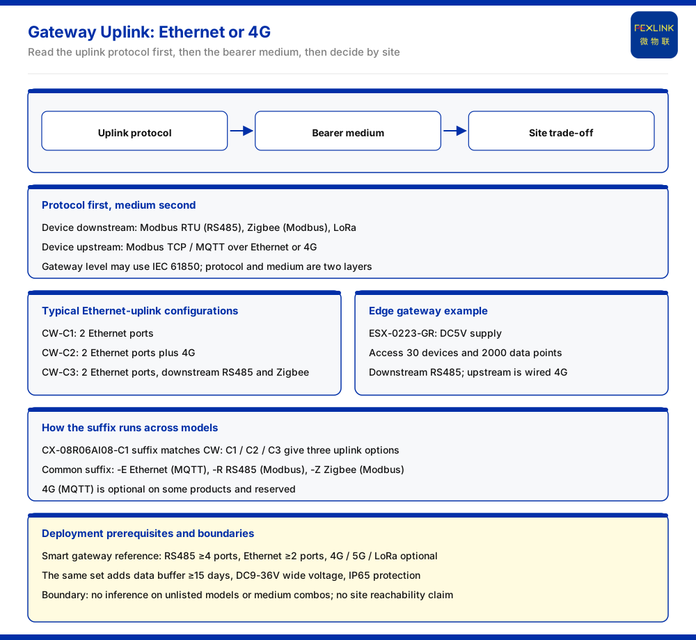
Whether a gateway should use Ethernet or 4G for its uplink depends on whether a usable wired network exists on site and whether link redundancy is required. The communication protocol matrix in the product knowledge base puts the device uplink at Modbus TCP and MQTT, carried over Ethernet and 4G; in the general suffix rules, 4G (MQTT) is marked as optional on some products and belongs to reserved capability. Coming down to specific models: the industrial gateway (CW-C1) is pure Ethernet uplink, the industrial gateway (CW-C2) is Ethernet plus 4G, and the intelligent edge-computing gateway (ESX-0223-GR) has a wired 4G uplink. In other words, where a stable wired network is available, Ethernet is the conventional choice, and wireless is used more for fallback or redundancy.
Read the uplink protocol first, then the medium
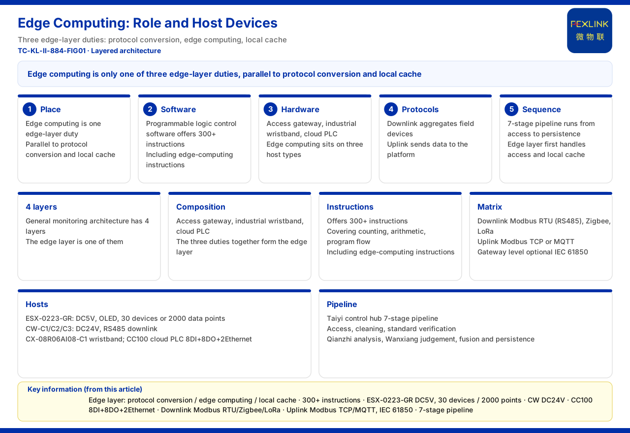
The communication protocol matrix in the product knowledge base specifies that the device downlink is Modbus RTU (RS485), Zigbee (Modbus) and LoRa; the device uplink is Modbus TCP and MQTT, carried over Ethernet or 4G; and the gateway level may optionally use IEC 61850. Selecting the uplink medium must first satisfy the requirement that the chosen medium can carry those uplink protocols. Separating protocol from medium avoids conflating "choosing a protocol" with "choosing a link": the protocol decides how data are expressed, the medium decides which path the data travel, and the two are different levels of question. The matrix states that the uplink protocols are carried over Ethernet or 4G; it does not state that every model offers every medium, so the model-level configuration still has to be read off the model table.
Typical Ethernet-uplink configurations
The CW industrial gateway offers three uplink configurations: CW-C1 is 2 Ethernet; CW-C2 is 2 Ethernet plus 4G; CW-C3 is 2 Ethernet, with RS485 and Zigbee supported on the downlink. Ethernet is therefore the base uplink medium of the CW series, with 4G appearing as an overlay. The intelligent edge-computing gateway (ESX-0223-GR) uses a DC5V supply, can connect 30 devices and 2000 data points, has RS485 as its downlink communication and wired 4G as its uplink communication. Reading the three CW versions together shows a common baseline and one extension item: the baseline is Ethernet in every case, and the difference between the versions lies in whether 4G is added on top. That is why Ethernet can be treated as the conventional uplink, with 4G as the variation.
How one suffix set runs through the models
The communication suffix is not unique to the CW series. The industrial wearable model example CX-08R06AI08-C1 defines its suffix the same way as the CW series: C1 is 2 Ethernet, C2 is 2 Ethernet plus 4G, and C3 is 2 Ethernet plus Zigbee, corresponding to the three uplink configurations. Reading the suffix correctly amounts to fixing the uplink medium first when selecting, and only then checking the remaining parameters.
The trade-off between 4G and redundancy
The general suffix rules specify that -E is Ethernet (MQTT), -R is RS485 (Modbus), and -Z is Zigbee (Modbus), and note that 4G (MQTT) is optional on some products and reserved. This means 4G is not standard on every model. Whether 4G is needed depends on whether a wired network exists and whether the site wants to keep a second uplink path beyond the primary link. Adding 4G is thus a decision about redundancy and fallback, not a default part of the uplink. Where no such second path is wanted, adding 4G would only add a component that is not exercised in normal operation.
Deployment preconditions given by the reference parameters
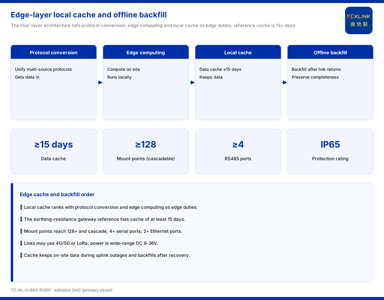
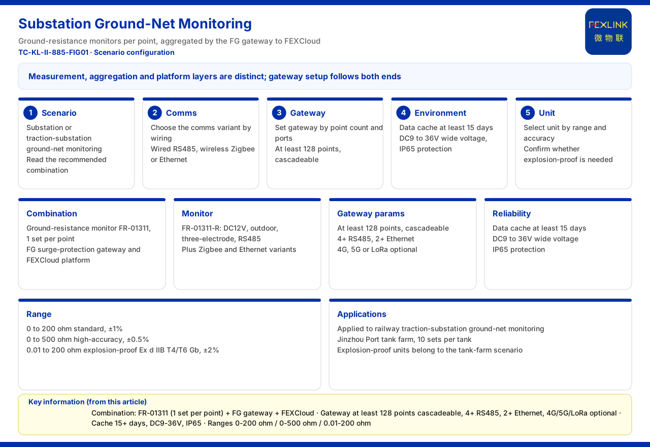
The smart gateway reference parameters for the grounding resistance monitoring system give RS485 not fewer than 4 channels, Ethernet not fewer than 2 channels, and 4G, 5G and LoRa optional. This shows that the uplink medium can be configured between Ethernet and wireless according to the site's network conditions. The same parameter set also includes a data cache of not fewer than 15 days, DC9 to 36V wide voltage and IP65 protection, as the deployment preconditions that still have to be met when a wireless uplink is used without a stable wired network. The data cache governs how long a record survives an interruption, the wide-voltage range governs the supply conditions the gateway tolerates, and IP65 governs the installation environment; together they set the boundary within which an uplink choice remains valid.
Weighing the choice by site conditions
Gathering the facts above, the trade-off can be organised around three questions. First, does the site have a stable, usable wired network: if so, Ethernet is the conventional uplink; if not, wireless has to be relied on. Second, is link redundancy needed: only when a second path is to be kept beyond the primary link does a configuration with 4G make sense. Third, are the deployment preconditions met: whether Ethernet or wireless is chosen, the channel counts of Ethernet and RS485, the data-cache days, the wide-voltage range and the protection rating must all be checked against the site. These three questions are not independent: the first decides whether wireless is needed at all, the second whether a redundant link is added on top, and the third whether the chosen configuration can actually be deployed.
Scope and limitations
First, this article restates only what the product knowledge base lists, and introduces no standard clause, parameter, certification or case that is not listed.
Second, the uplink configurations of the models discussed, the 30 devices and 2000 data points, the 2 Ethernet channels, the reserved 4G, RS485 not fewer than 4 channels, Ethernet not fewer than 2 channels, the data cache of not fewer than 15 days, DC9 to 36V and IP65 are all figures listed by the product knowledge base.
Third, this article makes no inference about unlisted models or medium combinations, and draws no conclusion about the network reachability of any site.
Fourth, actual deployment of wireless or wired links must be confirmed in conjunction with site network conditions, product access capability and the latest product documentation.