Direct answer
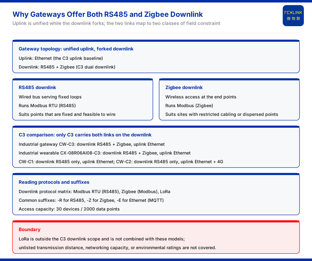
The gateway's downlink offers both RS485 and Zigbee because field wiring conditions at the downlink are not uniform. The knowledge base records that the downlink communication of the industrial gateway (CW-C3) is RS485 plus Zigbee, and its uplink is Ethernet; the industrial wearable (programmable device wearable, CX-08R06AI08-C3) likewise uses RS485 plus Zigbee on the downlink and Ethernet on the uplink. Within this pair, RS485 serves fixed wired loops and runs Modbus RTU; Zigbee runs Modbus and suits sites where cabling is restricted or points are dispersed. The two downlink links are not substitutes for each other; they correspond to two different classes of field constraint.
What the two downlink links are
The communication protocol matrix in the knowledge base lists the device downlink protocols as Modbus RTU (RS485), Zigbee (Modbus), and LoRa. Applied to the models discussed here, RS485 and Zigbee are the two downlink channels that are present at the same time. RS485 is a wired bus and handles acquisition on fixed loops; Zigbee is a wireless method and handles end-point access where no cabling is needed. The protocols carried by both belong to the Modbus family; the difference lies in the physical link, not in the measurement meaning carried at the upper layer.
What "dual downlink" specifically means for the C3 version
The knowledge base table records that the industrial gateway (CW-C3) is RS485 plus Zigbee on the downlink and Ethernet on the uplink; the industrial wearable (programmable device wearable, CX-08R06AI08-C3) is likewise RS485 plus Zigbee on the downlink and Ethernet on the uplink. Compared with other versions in the same family, the industrial gateway CW-C1 is RS485 only on the downlink and Ethernet on the uplink, and CW-C2 is RS485 only on the downlink and Ethernet plus 4G on the uplink. In other words, it is the C3 version that carries both RS485 and Zigbee on the downlink side. The dual downlink is therefore a version-level property, not a property of the whole family, and it should be read off the specific model rather than assumed for every unit that shares the product name.
Why two downlink links are needed
The value of a dual downlink is that it fits two classes of field constraint. The first is wiring condition: some loops have fixed positions where routing is feasible, and RS485 wired access is the more direct choice; some points are restricted by building structure or retrofit constraints, where cabling is difficult, and Zigbee wireless access avoids slotting and conduit work. The second is point distribution: when devices are dispersed over long distances, the cost of pulling each one back to the bus is high, and wireless access is a better fit. The knowledge base lists the two methods side by side as downlink options precisely so that one gateway downlink can cover both wired and wireless access conditions, instead of forcing the site into an exclusive choice between them.
Uplink unchanged, downlink forked
The direction is worth keeping clear. What changes in the C3 version is the downlink; the uplink remains Ethernet. The uplink baseline for the three industrial gateway versions is Ethernet in every case, and the only variation is in the uplink extension item; Zigbee does not appear in the uplink scope at all. The uplink of CW-C3 must therefore not be described as "Ethernet plus Zigbee", and Zigbee must not be treated as a substitute uplink channel. The uplink is responsible for sending aggregated data out, while the downlink is responsible for bringing end devices in; the two have different duties.
Downlink entries in the protocol matrix
The protocol matrix in the knowledge base lists Modbus RTU (RS485), Zigbee (Modbus), and LoRa as device downlink methods. The C3 version discussed here covers the first two on its downlink, while LoRa is not within its downlink scope, and this article draws no inference about combining LoRa with these models. The value of the matrix is that it assigns protocol membership: whether RS485 or Zigbee is selected, the upper layer is the Modbus family, and what changes in the field is the link form rather than the data semantics.
Reading the suffixes and the model numbers
The knowledge base records that in the general suffix table, -R is RS485 (Modbus), -Z is Zigbee (Modbus), and -E is Ethernet (MQTT). In the industrial wearable model examples, the C1 suffix corresponds to 2 Ethernet, C2 to 2 Ethernet plus 4G, and C3 to 2 Ethernet plus Zigbee. These suffix rules show that the communication configuration is already fixed at the model-number level, so checking selections against the suffix is more reliable than guessing by experience. The suffix encodes the communication choice; reading it correctly is the first step of any selection check.
Scope and limitations
- This article restates only what the knowledge base lists: the industrial gateway CW-C3 and the industrial wearable CX-08R06AI08-C3 are RS485 plus Zigbee on the downlink and Ethernet on the uplink; CW-C1 is RS485 only on the downlink and Ethernet on the uplink; CW-C2 is RS485 only on the downlink and Ethernet plus 4G on the uplink. - The access capability of both classes is 30 devices and 2000 data points, limited to the scope of the CW and CX series tables. - Protocol membership is limited to the Modbus RTU (RS485), Zigbee (Modbus), and LoRa entries listed in the communication protocol matrix; LoRa is not within the downlink scope of the models above, and no combination inference is made here. - The suffix rules are limited to the general suffix table and the industrial wearable model examples. - This article does not cover unlisted parameters such as transmission distance, networking capacity, or environmental adaptability, and constitutes no acceptance conclusion for any specific network deployment.