On site, one question recurs during gateway selection: how do you choose between an ESX intelligent edge-computing gateway (ESX-0223-GR) and a CW industrial gateway (CW-C1, CW-C2, CW-C3)? Both belong to the edge layer of a monitoring system, both acquire field data downward over RS485, and both share the same access capacity of 30 devices and 2000 data points. The real divide falls in three places: the power-supply format, the uplink network, and whether the downlink must provide Zigbee networking.
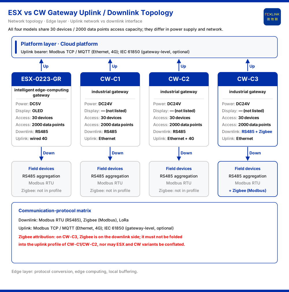
The conclusion comes first. If the cabinet supplies DC5V and data is uplinked to a cloud platform over wired 4G, the match is the edge-computing gateway (ESX-0223-GR): DC5V, OLED display, RS485 downlink, wired 4G uplink. If the site runs on DC24V with industrial Ethernet, the match is the industrial gateway family (CW-C1, CW-C2, CW-C3): all three are DC24V, RS485 downlink, 30 devices/2000 data points, and differ in expansion—CW-C1 uplinks over Ethernet, CW-C2 over Ethernet plus 4G, and CW-C3 adds Zigbee on the downlink alongside RS485 while still uplinking over Ethernet. Capacity is not the selection criterion; power supply and network are.
1. Place both device classes back in the edge layer
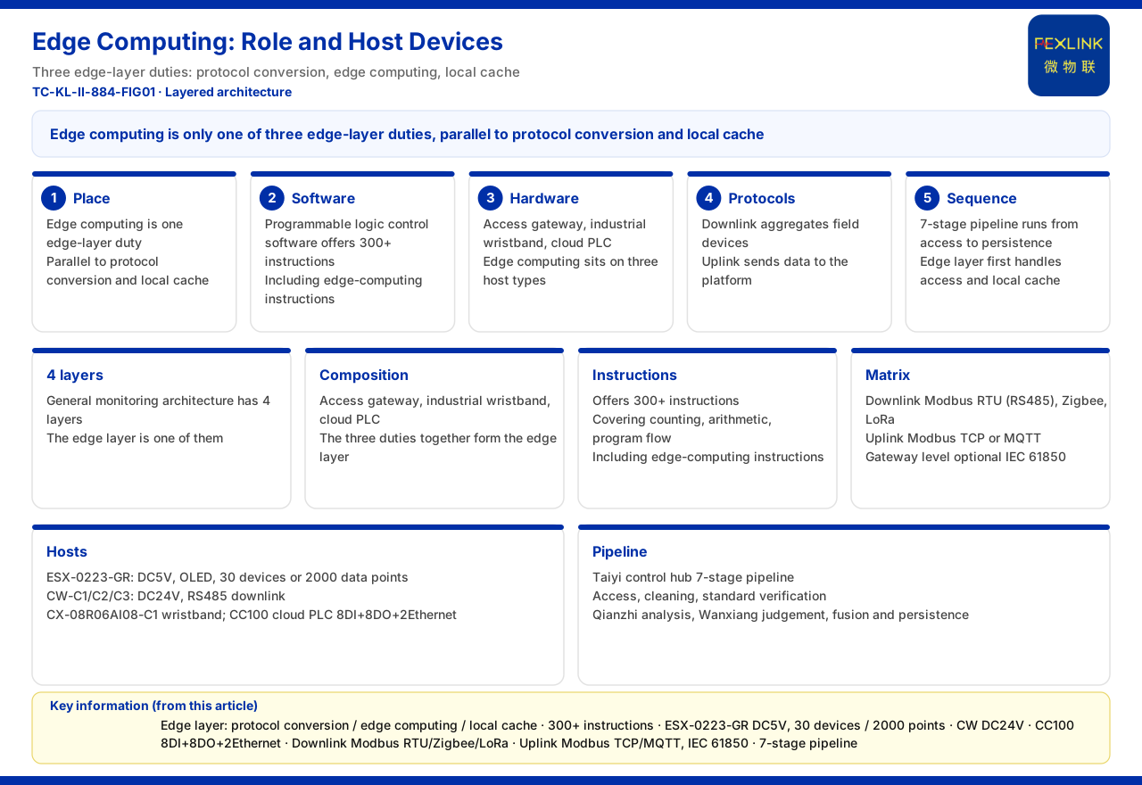
By the general four-layer architecture in the knowledge base, a monitoring system has perception, edge, platform, and application layers. The edge-computing gateway and the industrial gateway both sit in the edge layer, together with the FG lightning-protection smart gateway, the CX industrial wearable controller, and the CC cloud PLC. The edge layer carries protocol conversion, edge computing, and local caching.
Sharing a layer means they occupy the same position in the data link: downward they interface with field devices, upward with the platform layer. But the same position does not make them interchangeable, because each class has its own power-supply and network profile. Selection begins not with performance but by confirming what each device interfaces with at both ends of the link, then checking each parameter table item by item. Applying one product's parameters to another is the most common and most costly mistake in gateway selection.
2. Core parameter comparison
The table below consolidates the parameter-table entries of both device classes and is the basis for the rest of this article.
| Model | Power supply | Display | Access capacity | Downlink | Uplink | |:--|:--|:--|:--|:--|:--| | ESX-0223-GR | DC5V | OLED | 30 devices / 2000 data points | RS485 | Wired 4G | | CW-C1 | DC24V | — | 30 devices / 2000 data points | RS485 | Ethernet | | CW-C2 | DC24V | — | 30 devices / 2000 data points | RS485 | Ethernet + 4G | | CW-C3 | DC24V | — | 30 devices / 2000 data points | RS485 + Zigbee | Ethernet |
The table reveals a key fact: the access capacity of all four models is identical. When the site scale falls within that line, selection cannot be made on capacity but on power supply and network.
3. Criterion one: settle the power-supply format first
The edge-computing gateway is DC5V, and the industrial gateway is DC24V. These are not freely interchangeable equivalents; they correspond directly to the power-availability condition on the cabinet side. The most economical approach is to see which voltage the cabinet provides: with DC5V available and no DC24V condition, the range narrows to the edge-computing gateway; with a DC24V cabinet, selection turns to the industrial gateway family.
Power supply comes first because it is an existing site condition, usually fixed early and expensive to change.
4. Criterion two: how the uplink runs
On the uplink, the three industrial gateways share Ethernet; only CW-C2 adds 4G. CW-C3's Zigbee is downlink, not uplink; the edge-computing gateway runs wired 4G.
- Edge-computing gateway (ESX-0223-GR): uplink is wired 4G. - Industrial gateway CW-C1: uplink is Ethernet. - Industrial gateway CW-C2: uplink is Ethernet plus 4G. - Industrial gateway CW-C3: uplink is Ethernet.
One point needs emphasis: on the CW-C3 industrial gateway, Zigbee is on the downlink side, not the uplink side. Its uplink must not be described as "Ethernet plus Zigbee," and its Zigbee capability must not be folded into the uplink profile of the CW-C1 or CW-C2. Uplink and downlink are two directions, and the differences must be stated separately under each model.
The communication-protocol matrix clarifies the uplink bearer: the device uplink direction lists Modbus TCP / MQTT, which can run over Ethernet and 4G; it also lists IEC 61850, a gateway-level, optional capability. Whether Ethernet or 4G uplink is chosen, the upper-layer protocols fall within the same set of matrix entries; what varies is the physical bearer and the on-site link conditions.
5. Criterion three: downlink and Zigbee networking
All four models use RS485 as the downlink foundation, corresponding to Modbus RTU (based on RS485) in the protocol matrix. The only difference is CW-C3: its downlink is RS485 plus Zigbee. The matrix likewise lists Zigbee (Modbus) as a downlink method.
The logic is direct: if all field devices aggregate over RS485, RS485 downlink suffices; if some connect over Zigbee, Zigbee downlink must be considered, and CW-C3 is the model in this family with that capability. LoRa is also listed as a downlink method in the matrix, but it is not within the downlink profile of these four models, and this article draws no inference about combining it with them.
6. Combining the three criteria into one selection path
Running power supply, uplink, and downlink in order yields a clear path:
1. Confirm whether the available DC voltage is DC5V or DC24V. 2. If DC5V and the uplink must be wired 4G, choose the edge-computing gateway (ESX-0223-GR). 3. If DC24V, examine the uplink: choose the CW-C1 industrial gateway when Ethernet dominates; choose the CW-C2 when 4G is needed in addition; the CW-C3 also qualifies when Ethernet remains the uplink. 4. Examine the downlink: if Zigbee networking is required, choose the CW-C3 industrial gateway; if not, either the CW-C1 or CW-C2 will do. 5. Verify capacity: both device count and total data points must fall within 30 devices and 2000 points.
The order is not arbitrary. Power supply is the existing site condition hardest to change, so it comes first; the uplink determines how data leaves the site; the downlink is determined more by field device types.
7. Field checklist
1. Confirm cabinet power: DC5V or DC24V, and whether it matches the candidate model's profile. 2. Confirm uplink conditions: whether Ethernet and 4G coverage exist on site, and whether data is uplinked to the FEXCloud IoT cloud platform or another platform. 3. Confirm the uplink bearer: whether the chosen protocol is within the uplink matrix (Modbus TCP / MQTT); if IEC 61850 is involved, note that it is gateway-level and optional, subject to final configuration. 4. Confirm the downlink interface: whether field devices aggregate over RS485 and whether Zigbee devices also exist; if so, check CW-C3's RS485 + Zigbee downlink profile. 5. Verify access scale: count devices and data points and confirm both are within 30 devices and 2000 points. 6. Check the panel-observation requirement: the edge-computing gateway has an OLED display, while the industrial gateway parameter table lists no display item, so selection should follow the actual configuration.
The checklist uses only information already present in the parameter tables and the protocol matrix.
Scope and limitations
- This article is limited to the parameter rows of the intelligent edge-computing gateway (ESX-0223-GR) and the industrial gateway (CW-C1, CW-C2, CW-C3) in the knowledge base, and to existing entries in the four-layer architecture and the communication-protocol matrix. - The parameters are only those stated in the model tables: the edge-computing gateway is DC5V, OLED, 30 devices/2000 data points, RS485 downlink, wired 4G uplink; the three industrial gateway models are all DC24V, RS485 downlink, 30 devices/2000 data points, with uplinks of Ethernet, Ethernet + 4G, and Ethernet, and CW-C3's downlink being RS485 + Zigbee. This does not include performance, certification, environmental, or field-case conclusions beyond the tables. - Zigbee attribution must be stated separately: CW-C3's Zigbee is on the downlink side and must not be folded into the uplink profile of CW-C1 or CW-C2, nor should ESX and CW variants be conflated on that basis. - Modbus, MQTT, IEC 61850, LoRa, and other names from the protocol matrix are cited as listed in the knowledge base, where IEC 61850 is gateway-level and optional; which item a project adopts is subject to engineering configuration. - The knowledge base's standard service provides a library of 408 standards (covering 12 systems such as GB/GB-T/DL/IEC/UL) with automatic clause matching; GB/T 16895 is cited only as referenced in the knowledge base, and this article does not present it as a compliance determination for any product. - This article does not constitute a commitment regarding any unlisted metric; where site conditions differ from the premises here, the latest product documentation and actual engineering solution prevail.